Understanding 4-Way Switch Wiring
Navigating four-way switch setups can be complex‚ as there is no standard diagram universally followed for these circuits.
Understanding these nuances is crucial for successful installation and troubleshooting‚ especially when dealing with older NM copper wiring configurations.
Resources like Reddit’s r/electrical and Home Improvement Stack Exchange highlight the challenges and variations encountered in 4-way switch wiring‚ emphasizing the need for careful observation and replication of existing connections.
Four-way switches are essential components in electrical circuits allowing control of a single light fixture from three or more locations. Unlike simpler setups‚ they don’t directly break or complete the circuit; instead‚ they redirect the electrical flow through “traveler” wires. This redirection capability is what enables operation from multiple points.
The complexity arises because there isn’t a single‚ standardized wiring diagram for 4-way switches. Installations often vary based on how the initial 3-way switches are configured and where the power source (line) and light fixture (load) are located. Online forums‚ such as those on Reddit and Stack Exchange‚ frequently discuss these variations.
Older homes with NM copper wiring‚ particularly using 12/3 or 14/3 cabling‚ commonly employ 4-way switches. Successfully replacing or installing these requires understanding the existing wiring scheme and meticulously replicating it. Resources emphasize the importance of being able to restore the original configuration if unsure‚ and caution against relying on generic diagrams.
What is a 4-Way Switch?
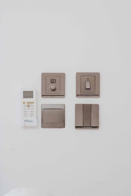
A 4-way switch is a specific type of electrical switch designed to be used in conjunction with two 3-way switches‚ enabling control of a light or fixture from at least three locations. It doesn’t have “on” or “off” positions like a standard switch; instead‚ it alters the path of electricity between two “traveler” wires.
Visually‚ a 4-way switch typically features four terminals (excluding the ground). These terminals are arranged in pairs‚ and the switch internally connects one pair to the other‚ effectively changing the circuit’s route. This internal switching action is what allows for multi-location control.
Understanding that no standard wiring diagram exists is crucial. Configurations depend heavily on the existing 3-way switch setup and the location of the power source and light. Discussions on platforms like Reddit highlight that simply matching wire colors to terminals is often the most reliable approach when replacing a 4-way switch‚ particularly in older homes with NM copper wiring.
Applications of 4-Way Switches
4-way switches excel in scenarios demanding lighting control from multiple points‚ most commonly found in hallways‚ stairwells‚ and large rooms with entrances at opposite ends. Imagine controlling a hallway light from the top and bottom of the stairs – this is a prime application.
Beyond residential settings‚ they’re useful in larger spaces like offices or workshops where convenient access to lighting controls is paramount. The ability to turn a light on at one entrance and off at another enhances both convenience and security.
However‚ implementing these systems requires careful consideration‚ as the wiring can be more intricate than standard setups. Online forums‚ such as Home Improvement Stack Exchange‚ emphasize the lack of a universal 4-way switch wiring diagram‚ meaning each installation may require a tailored approach. Successfully utilizing 4-way switches often involves replicating existing wiring configurations‚ especially in older homes utilizing NM copper wiring.
Essential Components & Wiring Basics
Understanding the terminals and wire colors is vital for 4-way switch wiring‚ often involving 12/3 or 14/3 NM copper wiring.
Careful identification is key to success.
Identifying 4-Way Switch Terminals
Four-way switches differ significantly from standard single-pole or three-way switches in their terminal arrangement. Unlike the common/traveler setup of 3-way switches‚ 4-way switches feature four traveler terminals and a common terminal. These traveler terminals are typically arranged in pairs on opposite sides of the switch body.
Identifying these terminals is crucial before beginning any wiring work. The common terminal is often a different color than the traveler terminals – frequently dark or black. The traveler terminals are usually brass-colored. It’s important to note that screw color isn’t a reliable indicator‚ as manufacturers can vary.
Carefully observe the existing wiring before disconnecting anything. Note which wires are connected to which terminals. Taking pictures can be incredibly helpful. The goal is to replicate the existing connections accurately when installing the new switch. Remember‚ the absence of a standard diagram necessitates meticulous attention to detail when tracing the existing wiring configuration.
Common Wire Colors Used in 4-Way Switch Circuits
Understanding wire colors is fundamental to safely and correctly wiring a 4-way switch circuit. Typically‚ NM copper wiring (often 12/3 or 14/3) is used in these setups. This cable contains a black (hot)‚ white (neutral)‚ and red (traveler) wire‚ plus a bare copper or green ground wire.
The black wire usually carries the power source (line) to the first switch. The white wire is generally used as a neutral‚ though it can sometimes be re-identified as a hot wire in specific configurations. Red and another color wire (often black or blue) serve as the traveler wires‚ connecting the two 3-way switches to the 4-way switches.
However‚ it’s vital to remember that wire color conventions aren’t always strictly followed‚ especially in older installations. Always verify the function of each wire with a voltage tester before making any connections. Accurate identification prevents dangerous miswiring and ensures the circuit functions as intended.
The Role of Traveler Wires
Traveler wires are the cornerstone of 4-way switch functionality‚ enabling control of a light fixture from multiple locations. These wires‚ typically red and another color (often black)‚ connect the two 3-way switches through the 4-way switch(es).
Their purpose is to “carry” the electrical current’s path between the 3-way switches‚ allowing either switch to interrupt or complete the circuit‚ regardless of the other’s position. The 4-way switch doesn’t break or complete the circuit itself; it merely redirects the traveler wires.
Effectively‚ the 4-way switch swaps the connections of the traveler wires‚ changing which 3-way switch is “active” in the circuit. Correctly identifying and connecting these traveler wires is paramount for proper operation. Miswiring them will result in unpredictable behavior or a non-functional circuit‚ highlighting the importance of careful attention during installation.

Step-by-Step Wiring Guide
Due to the lack of a standardized 4-way switch diagram‚ meticulous documentation of the existing wiring is essential before disassembly. Careful replication is key!
Wiring Diagram Overview (No Standard Diagram)
Unlike simpler circuits‚ a universally accepted‚ standardized wiring diagram for 4-way switches simply doesn’t exist. This is a critical point often emphasized in online discussions‚ such as those found on Home Improvement Stack Exchange. The wiring configurations can vary significantly depending on how the initial installation was performed.
Consequently‚ relying on generic diagrams can be misleading and potentially lead to incorrect wiring. Instead‚ the most reliable approach involves thoroughly documenting the existing wiring before disconnecting anything. This documentation should include noting the wire colors connected to each terminal on all switches involved – the two 3-way switches and the two 4-way switches.
Photographs are invaluable in this process. The goal is to be able to recreate the original connections precisely. Remember that 12/3 or 14/3 NM-B copper wiring is commonly found in these setups‚ indicating the presence of traveler wires. Without a clear understanding of the original layout‚ troubleshooting becomes significantly more difficult.
Connecting the Power Source (Line)
The “line” wire‚ carrying power from the electrical panel‚ is typically connected to one of the 3-way switches‚ not directly to a 4-way switch. Identifying the line wire is crucial for safety and proper functionality. It’s usually a black wire‚ but always verify with a non-contact voltage tester before making any connections.
This line wire connects to the “common” terminal on the first 3-way switch. The common terminal is often a different color than the other two terminals – typically black or dark-colored. Ensure the power is OFF at the breaker before working with any wiring.
Carefully note how the line wire is connected; this is vital for recreating the circuit correctly. In scenarios where the line and load are in the same box (as discussed in SmartThings Community forums regarding GE Z-Wave switches)‚ the wiring becomes more complex and requires extra caution and detailed documentation.
Connecting the Light Fixture (Load)
The “load” wire‚ which powers the light fixture itself‚ connects to the “common” terminal of the second 3-way switch. Similar to the line wire‚ the load is often a black wire‚ but confirmation with a voltage tester is essential. This connection completes the circuit‚ allowing the switches to control the flow of electricity to the light.
Before connecting‚ ensure the power is completely shut off at the breaker. Carefully observe the existing wiring configuration‚ as variations can occur‚ especially in older homes with NM copper wiring. Documenting the connections before disconnecting anything is highly recommended‚ particularly given the lack of a standardized 4-way switch diagram.
Properly securing the load wire to the common terminal is vital for a safe and reliable connection. Incorrect wiring can lead to flickering lights or‚ worse‚ a fire hazard.
Wiring the First 3-Way Switch
Begin by connecting the power source – the “line” wire – to one of the traveler terminals on the first 3-way switch. Typically‚ this is a black wire‚ but always verify with a voltage tester before making any connections. The remaining traveler terminal receives the other traveler wire‚ which will run to the second 3-way switch.
The common terminal on this first switch will not connect directly to the light fixture. Instead‚ it’s crucial to remember this switch acts as an intermediary‚ directing power along the traveler wires. Given the absence of a standard 4-way diagram‚ meticulous attention to matching existing wire colors and terminal positions is paramount.
Securely fasten all connections‚ ensuring no bare wire is exposed; A loose connection can cause intermittent operation or a potential safety hazard.
Wiring the Second 3-Way Switch
Similar to the first 3-way switch‚ connect the traveler wires arriving from the first switch to the traveler terminals on this second switch. Maintaining consistent color-coding is vital for proper functionality. The common terminal on this second 3-way switch is where you’ll connect the wire leading to the first 4-way switch.
Remember‚ the goal is to create a continuous path for electricity to flow‚ controlled by the combined action of all four switches. As emphasized by online resources‚ replicating the existing wiring configuration is key‚ especially given the lack of a standardized 4-way switch diagram.
Double-check all connections for tightness and ensure no bare wires are exposed. Proper insulation is crucial for safety and reliable operation.
Connecting the Two 4-Way Switches
The two 4-way switches are interconnected using traveler wires. These aren’t simply connected to the common terminals; instead‚ they utilize all four terminals on each switch. Connect the traveler wires from the first 4-way switch to the corresponding traveler terminals on the second 4-way switch – matching is crucial.
Online discussions‚ like those on Home Improvement Stack Exchange‚ stress the importance of understanding that 4-way wiring deviates from standard diagrams. Carefully observe the existing wiring‚ noting the color scheme and terminal connections. Replicate this precisely on the new switches.
Ensure secure connections and proper insulation. Incorrect wiring can lead to malfunctions or safety hazards. Remember‚ the traveler wires facilitate the switching action between the two 3-way switches.

Troubleshooting Common Issues
Identifying incorrect wiring is key‚ as 4-way circuits lack a standard diagram. Issues with GE Z-Wave switches‚ or line/load in the same box‚ require careful diagnosis.

Identifying Incorrect Wiring
Diagnosing wiring errors in a 4-way switch circuit demands a systematic approach‚ given the absence of a universally accepted standard diagram. Begin by meticulously comparing the existing wiring configuration to any notes or photographs taken before disassembly. A common mistake involves misidentifying traveler wires; these are crucial for proper functionality and should be connected consistently across all switches.
If the lights don’t operate as expected – perhaps only working from one switch location‚ or failing to turn off completely – carefully re-examine the connections. Ensure that the power source (line) and the light fixture (load) are correctly identified and wired to the appropriate terminals on the 3-way switches. Online forums‚ like those on Reddit (r/electrical)‚ often discuss similar issues‚ providing valuable insights from experienced users.
Remember that incorrect wiring can not only cause inconvenience but also pose a safety hazard. If you are uncomfortable or unsure about any aspect of the wiring process‚ it is always best to consult a qualified electrician.
Dealing with Line and Load in the Same Box
Situations where both the power source (line) and the light fixture (load) reside within the same electrical box present a unique challenge in 4-way switch wiring. This configuration‚ while not ideal‚ is sometimes encountered in older homes or during renovations. Successfully navigating this requires careful attention to detail and a clear understanding of how traveler wires function.
The SmartThings Community forums highlight the complexities of wiring GE Z-Wave switches in such scenarios‚ emphasizing the need for a specific wiring approach. Typically‚ the line and load are connected to one of the 3-way switches‚ while the remaining two switches (the 4-ways) handle the traveler wires.
Accurate identification of these wires is paramount. Incorrect connections can lead to unpredictable behavior or even a short circuit. Always double-check your work against any existing diagrams or notes‚ and if uncertainty persists‚ consult a qualified electrician to ensure a safe and functional installation.
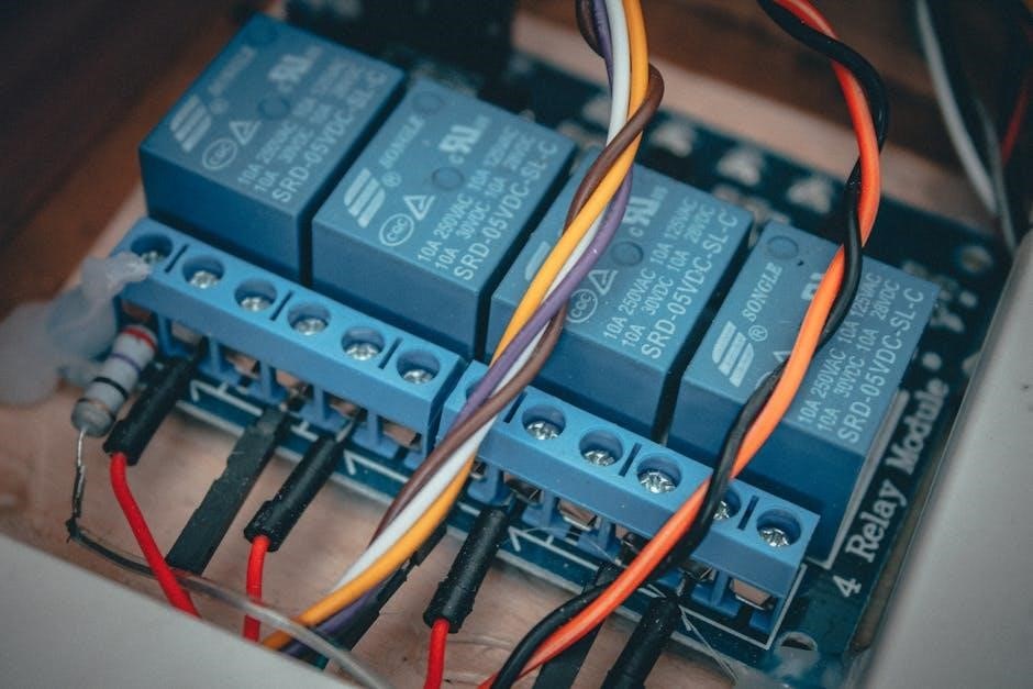
Addressing Issues with GE Z-Wave Switches
Integrating GE Z-Wave switches into a 4-way circuit introduces specific considerations due to their smart functionality and wiring requirements. The SmartThings Community frequently discusses challenges encountered when using a GE master switch paired with two auxiliary switches in a 4-way setup‚ particularly when the line and load are within the same box.
Common issues often stem from incorrect traveler wire connections or improper configuration within the Z-Wave network. Ensuring the master switch is correctly identified and paired is crucial. Auxiliary switches rely on the master for communication and control‚ so any disruption in this link can cause malfunctions.

Carefully review the GE Z-Wave switch documentation and wiring diagrams. If problems persist‚ resetting the switches and re-pairing them to the hub can often resolve connectivity issues. Remember to consult online forums and support resources for specific troubleshooting steps related to GE Z-Wave devices.
Advanced Considerations
Complex setups‚ like 16-way dial switches or Godown wiring diagrams with three switches‚ demand a thorough understanding of traveler wires and terminal functions (XT1)‚ especially with NM copper wiring.
Wiring with NM Copper Wiring (12/3 or 14/3)
When encountering NM copper wiring – specifically 12/3 or 14/3 – in a 4-way switch circuit‚ it indicates a more modern wiring approach. This cable contains four current-carrying conductors plus a ground‚ facilitating the necessary connections for the traveler wires crucial to 4-way functionality.
The Reddit discussion highlights that homes with this wiring often utilize a 4-way switch setup‚ meaning replacing an existing switch simply requires obtaining another 4-way switch and meticulously matching the wire connections based on screw color. This simplifies the process‚ as the existing wiring is already configured correctly for a 4-way system.

However‚ careful attention must be paid to identifying the traveler wires and ensuring they are connected to the corresponding terminals on the new switch. Incorrect wiring can lead to malfunctioning lights or‚ in worst-case scenarios‚ electrical hazards. Always double-check connections against the original configuration before restoring power.
Godown Wiring Diagrams (3 Switch Configurations)
The referenced documentation summarizes a “godown wiring diagram” featuring three switch configurations‚ likely representing variations within a larger electrical system. While specifics are limited without the full diagram‚ this suggests a complex setup potentially incorporating multiple 4-way switches or combinations of 3-way and 4-way switches to control lighting from various locations.
Understanding these configurations requires careful analysis of the wiring layout‚ identifying the power source (line)‚ the light fixture (load)‚ and the traveler wires connecting the switches. The diagram likely illustrates how these components interact to achieve the desired switching functionality.
It’s important to note that these “godown” diagrams may not adhere to standard wiring practices‚ necessitating a thorough understanding of electrical principles and a cautious approach to troubleshooting or modifications. Accurate documentation and careful tracing of wires are essential when working with non-standard wiring schemes.
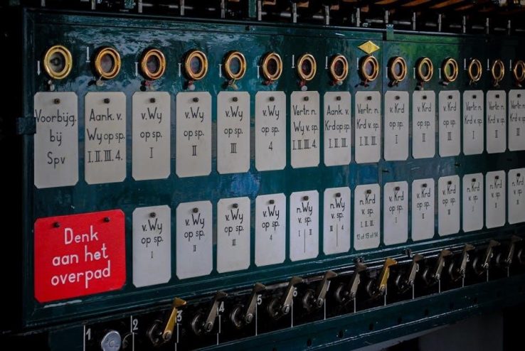
16-Way Dail Switch Function & 4-Way Terminal (XT1)
The documentation briefly mentions a “16-WAY DAIL SWITCH FUNCTION” alongside a “4-WAY TERMINAL (XT1)”. This suggests a highly complex switching system‚ far beyond typical residential setups. The “XT1” terminal likely refers to a specific connection point on the switch‚ potentially used for controlling a large number of lights or circuits.
The reference to “S1 DAIL SWITCH” and associated addresses (A BO. N. WHITE. BLUE. Y/G) indicates a coded system for identifying switch positions or functions within the 16-way configuration. Understanding this coding is crucial for interpreting the switch’s operation.
Furthermore‚ the mention of “SHORT W1 AND W2. LOW VOLTAGE SIGNAL” suggests the system may utilize low-voltage control signals to manage the extensive switching network. This type of setup is likely found in industrial or commercial applications requiring precise control over numerous lighting zones.