nikon d5200 instruction manual

Welcome to the Nikon D5200 manual, your guide to mastering this versatile DSLR camera. This comprehensive guide covers everything from basic controls to advanced photography techniques.

Overview of the Nikon D5200 Camera

The Nikon D5200 is a versatile DSLR camera designed for both beginners and advanced photographers. It features a 24.1MP CMOS sensor, EXPEED 3 processor, and an ISO range of 100-6400. The camera supports Full HD video recording, manual controls, and compatibility with Nikon F-mount lenses. Its intuitive interface and advanced autofocus system make it ideal for capturing high-quality images in various lighting conditions. The D5200 also offers a range of shooting modes, wireless connectivity, and expandability with optional accessories.

Key Features and Benefits

The Nikon D5200 offers a 24.1MP CMOS sensor and EXPEED 3 image processor, delivering sharp images with excellent low-light performance. It features a 3-inch vari-angle LCD screen for flexible composition and Full HD video recording at 1080p. The camera supports manual controls, wireless connectivity, and compatibility with a wide range of NIKKOR lenses. Its intuitive interface and advanced autofocus system ensure precise focus, while Scene Modes and Effects provide creative flexibility for photographers of all skill levels.

Camera Specifications

The Nikon D5200 features a 24.1MP CMOS sensor, EXPEED 3 processor, and ISO 100-6400 sensitivity. It supports 1080p Full HD video and has a 3-inch LCD screen.

Technical Specifications of the Nikon D5200

The Nikon D5200 features a 24.1-megapixel APS-C CMOS sensor and EXPEED 3 image processor, delivering high-quality images. It offers an ISO range of 100-6400, expandable to 25600. The camera supports continuous shooting at 5 fps and records 1080p Full HD video at 60i/50i/30p/25p. A 3-inch, 921k-dot vari-angle LCD provides flexible composition. With 39 autofocus points, it ensures precise subject tracking. The D5200 accepts SD/SDHC/SDXC memory cards, enabling ample storage for photos and videos.

Lens Compatibility and Accessories

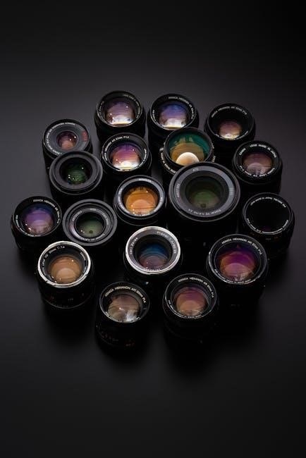
The Nikon D5200 is compatible with Nikon F-mount lenses, including AF and AF-P models for autofocus functionality. It supports a wide range of Nikkor lenses, from wide-angle to telephoto, enhancing versatility. Accessories like the MB-D12 battery grip extend shooting capacity, while the WU-1a Wi-Fi adapter enables wireless connectivity. Additional options include external microphones for video recording and compatible Speedlights for advanced lighting. Manual focus lenses can also be used with the camera’s electronic rangefinder for precise control.

Shooting Modes

The Nikon D5200 offers versatile shooting modes, including Auto, Manual, Aperture Priority, and Shutter Priority, catering to both beginners and advanced photographers. Scene Modes and Effects enhance creativity.

Understanding Auto Modes

The Nikon D5200 features multiple Auto Modes, including Scene Modes and Effects, designed to simplify photography. Auto Mode adjusts exposure, ISO, and focus automatically, making it ideal for beginners. Scene Modes, like Portrait and Landscape, optimize settings for specific subjects. Effects, such as Night Vision and Pop Art, add creative flair. These modes allow users to capture high-quality images without manual adjustments, while still offering flexibility for those exploring advanced techniques.

Using Aperture Priority, Shutter Priority, and Manual Modes

Aperture Priority (A/Av) allows control over aperture, with the camera adjusting shutter speed. Shutter Priority (S/Tv) lets you set shutter speed, ideal for freezing or blurring motion. Manual (M) mode offers full control over both aperture and shutter speed for precise results. These modes enable creative freedom, catering to advanced photographers who want to experiment with lighting, depth of field, and motion effects in various shooting scenarios.

Video Recording Modes and Settings

The Nikon D5200 offers versatile video recording options, including 1080p and 720p resolutions at frame rates of 24p, 25p, and 30p. Manual movie settings allow control over aperture, shutter speed, and ISO for creative freedom. The camera supports external microphones for enhanced audio quality and features a headphone jack for real-time monitoring. These modes and settings make the D5200 ideal for capturing high-quality video with precise control over both visual and auditory elements.

Menu System

The Nikon D5200 features an intuitive menu system, offering easy navigation and customization options to tailor settings for personalized shooting experiences and enhanced camera functionality.

Navigating the Camera Menu

Navigating the Nikon D5200 menu system is straightforward, with options organized into user-friendly categories. Access the menu by pressing the Menu button, then use the multi-selector to scroll through options like shooting settings, playback, and setup. The INDEX.pdf file provides a detailed guide to menu items. Customize settings for personalized use, such as adjusting autofocus modes or video recording options. Troubleshooting tips are also available within the menu system for quick solutions. Use the Nikon Manual Viewer 2 app for easy reference on your device.

Customizing Settings for Personalized Shooting

Customize your Nikon D5200 to match your photography style by adjusting settings like autofocus modes, metering options, and exposure compensation. Assign frequently used functions to camera buttons for quick access. Use the multi-selector to navigate through the menu and tailor options such as white balance, ISO sensitivity, and bracketing. Save preferred configurations for instant recall during shoots, ensuring a personalized and efficient workflow.

  • Assign functions to camera buttons for quick access.
  • Adjust autofocus modes and metering systems.
  • Customize white balance, ISO, and exposure settings.
  • Save configurations for personalized workflows.

Advanced Features

The Nikon D5200 offers advanced autofocus and metering systems, plus features like bracketing and interval shooting, enabling precise control over your photography experience.

Autofocus and Metering Systems

The Nikon D5200 features an advanced autofocus system with Nikon’s Multi-CAM 4800DX sensor, offering 39 focus points for precise subject tracking. The camera also includes the Scene Recognition System, which enhances metering and autofocus accuracy by analyzing the scene. With improved low-light performance, the D5200 delivers reliable focusing down to -1 EV. Additionally, the electronic rangefinder supports manual focus operations, ensuring sharp results in challenging conditions.

Using Bracketing and Interval Shooting

The Nikon D5200 supports bracketing and interval shooting for advanced photography. Bracketing captures multiple shots at different exposures, ideal for HDR imaging. Interval shooting allows you to take photos at set intervals, perfect for time-lapse sequences. The camera can shoot up to 999 frames at intervals of 1 second to 24 hours. These features enhance creative control and simplify capturing dynamic scenes or long-term changes in your environment.

Video Recording

The Nikon D5200 supports Full HD video at 1080p with frame rates up to 60i. Manual movie settings and stereo microphone input enhance recording flexibility and audio quality.

Configuring Movie Settings

Configuring movie settings on the Nikon D5200 allows for precise control over video recording. Select frame rates up to 60i and resolutions up to Full HD 1080p. Manual movie settings enable adjustment of exposure, ISO, and audio levels. The camera also supports stereo microphone input for enhanced sound quality. Additional features include focus modes optimized for video and customizable controls for a tailored shooting experience.

Using External Microphones and Accessories

Enhance your Nikon D5200 experience with external microphones and accessories. The camera features a stereo microphone input for high-quality audio recording. Additional ports, including HDMI and USB/AV output, allow connection to external devices. Compatible accessories like remote controls, GPS units, and external flashes expand functionality. Use the Nikon Manual Viewer 2 app or Adobe Reader to explore detailed guides for optimizing these features, ensuring professional-grade performance and versatility in your photography and videography projects.

Connectivity and Software

The Nikon D5200 offers seamless connectivity with HDMI and USB/AV output for easy file transfer and device connection. Use Nikon software for advanced image editing and management.

Connecting to Computers and Other Devices

The Nikon D5200 supports various connectivity options, including HDMI and USB/AV output for easy transfer of images and video to computers or external devices. Use the USB cable provided to connect directly to your computer or import photos via card readers. Additionally, the optional WU-1a Wireless Mobile Adapter enables wireless transfer to smartphones or tablets, making sharing convenient. Ensure your devices are compatible with the camera’s ports for seamless connectivity and efficient file management.

Using Nikon Software for Image Editing

Nikon offers powerful software tools like ViewNX-i and Capture NX-D for editing images captured with the D5200. ViewNX-i allows easy management and basic editing of photos, while Capture NX-D provides advanced RAW image processing. These programs enable adjustments to exposure, color balance, and noise reduction, helping you enhance image quality. They are designed to be user-friendly, catering to both beginners and experienced photographers aiming for professional results.

Customization and Control

The Nikon D5200 offers extensive customization options, allowing users to tailor settings and controls to their preferences for a more intuitive and personalized shooting experience.

Customizing Camera Buttons and Controls

The Nikon D5200 allows users to assign custom functions to specific buttons, enhancing workflow efficiency. By navigating to the Custom Setting Menu, photographers can reconfigure controls like the Fn button or AE-L/AF-L button to access frequently used settings. This feature enables a personalized shooting experience, streamlining operations and improving responsiveness during critical moments. Customization options ensure the camera adapts to individual preferences, making it an intuitive tool for both beginners and advanced photographers.

Creating Custom Menus

The Nikon D5200 enables users to create custom menus, streamlining access to frequently used settings. By organizing preferred options into a personalized menu, photographers can save time and enhance workflow. This feature is particularly useful for accessing shooting modes, autofocus settings, and image quality preferences quickly. Custom menus are easily created via the camera’s menu system, allowing for a tailored and efficient shooting experience tailored to individual needs and preferences.

Troubleshooting and Maintenance

Address common issues like error messages or sensor cleaning. Regularly update firmware and reset settings to default if problems persist. Proper maintenance ensures optimal camera performance and longevity.

Common Issues and Solutions

Address common issues like error messages, sensor cleaning, or autofocus malfunctions. Update firmware regularly to resolve bugs and improve performance; For lens errors, ensure proper mounting and clean contacts. Reset settings to default if camera behavior is unstable. Clean the sensor gently with approved tools to avoid dust spots. Consult the manual or Nikon support for detailed troubleshooting steps to maintain optimal functionality and image quality.

Cleaning and Maintaining the Camera

Regularly clean the camera sensor with a soft brush or approved cleaning solutions to prevent dust spots. Use a microfiber cloth to wipe the lens and camera body, avoiding harsh chemicals. Check and update firmware to ensure optimal performance. Store the camera in a dry, cool place to prevent moisture damage. Clean the lens with a UV filter for added protection. Refer to the manual for detailed maintenance instructions to keep your Nikon D5200 in excellent condition.

Additional Resources

Access the official Nikon website for downloadable PDF manuals, firmware updates, and software tools. Utilize the Nikon Manual Viewer 2 app for mobile access to guides and tutorials.

Downloading the Nikon D5200 Manual

The Nikon D5200 manual is available for free download from Nikon’s official website or trusted sources like ManualsLib. The manual is provided in PDF format and covers all aspects of the camera, including setup, shooting modes, and advanced features. To download, visit the Nikon support page, select your camera model, and choose the manual or reference guide. Ensure to download from reliable sources to avoid unauthorized content. The manual is also accessible via the Nikon Manual Viewer 2 app for mobile devices, offering convenience for on-the-go reference.

Online Tutorials and Guides

Online tutorials and guides for the Nikon D5200 are widely available, offering step-by-step instructions and hands-on demonstrations. Platforms like YouTube feature detailed playlists covering everything from basic setup to advanced techniques. Nikon’s official website and third-party sites like ManualsLib provide downloadable PDF manuals and reference guides. Additionally, forums and photography communities share user-generated tips and troubleshooting advice, making it easier for photographers of all skill levels to master the D5200’s features and improve their photography skills.

cobra 29 lx cb radio manual

The Cobra 29 LX CB Radio is a high-performance, 40-channel CB radio designed for reliable communication on the go. Its advanced features, including weather alerts and noise reduction, ensure clear and consistent connectivity. The user manual is essential for understanding installation, operation, and customization options, helping users maximize their radio’s potential. This guide provides a comprehensive overview to help you get started and make the most of your Cobra 29 LX CB Radio experience.

1.1 Overview of the Cobra 29 LX CB Radio

The Cobra 29 LX CB Radio is a 40-channel CB radio designed for reliable communication in vehicles. It features instant access to emergency channel 9 and weather alerts, ensuring safety and convenience. Its compact design and user-friendly interface make it ideal for drivers seeking clear and efficient communication on the go.

1.2 Importance of the User Manual

The user manual is essential for understanding the Cobra 29 LX CB Radio’s features, installation, and operation. It provides detailed instructions for troubleshooting, optimizing performance, and ensuring compliance with legal requirements. Reading the manual helps users maximize the radio’s potential, operate it safely, and resolve issues efficiently, making it a vital resource for owners.

Key Features of the Cobra 29 LX CB Radio

The Cobra 29 LX CB Radio offers 40 channels, NOAA weather alerts, and emergency channel access. It features customizable sound settings, noise reduction, and a large LCD display for easy operation.

2.1 Channels and Frequency Range

The Cobra 29 LX CB Radio operates on 40 AM channels within the 26.965 MHz to 27.255 MHz range. It supports both AM and SSB modes, offering clear communication across all frequencies. The radio’s channel selector allows quick switching, ensuring easy access to emergency channels and standard CB frequencies for reliable connectivity on the go.

2.2 Weather and Emergency Features

The Cobra 29 LX CB Radio includes a built-in NOAA Weather Radio, allowing users to receive critical weather alerts and emergency information. It also features instant access to emergency channels (9 and 19), ensuring quick communication during critical situations. The radio’s weather alert system provides real-time updates, keeping you informed and prepared for severe weather conditions.

2.3 Sound and Audio Settings

The Cobra 29 LX CB Radio offers adjustable squelch control to minimize background noise and enhance clarity. The RF gain feature allows fine-tuning of signal strength for optimal reception. Additionally, the radio includes a dynamic microphone with clear audio output, ensuring high-quality communication. These settings enable users to customize their listening experience for better sound quality and reduced interference.

Installation and Setup

Mounting the Cobra 29 LX CB Radio securely is essential for stability and performance. Proper wiring to a 12V power source and grounding ensures reliable operation. Follow the manual’s guidelines for antenna placement and connection to optimize signal strength and reception quality.

3.1 Mounting the Radio

Mounting the Cobra 29 LX CB Radio securely ensures optimal performance. Choose a stable location, such as the dashboard or under-dash area, using the provided mounting hardware. Ensure the surface is clean and flat for proper adhesion. Position the radio to maintain accessibility and visibility, keeping it away from moving parts or heat sources. Secure the unit firmly to avoid vibration and ensure reliable operation. Neatly route power and antenna cables to prevent interference and tangling. Double-check all connections for stability and proper function before finalizing the installation.

3.2 Wiring and Power Supply

Connect the Cobra 29 LX CB Radio to a 12V DC power source using the provided wiring harness. Ensure the red wire is connected to the positive terminal and the black wire to ground. Install a fuse near the battery to protect against power surges. Secure all connections tightly to avoid interference. Verify polarity and test the power supply before full operation to ensure proper function and prevent damage. Always follow safety guidelines to prevent electrical hazards.

3.3 Antenna Installation

Select a suitable location for the antenna, ensuring optimal signal reception. Mount the antenna securely, preferably on a metal surface, and connect it to the radio’s antenna port. Properly ground the antenna to minimize interference and ensure safety. Use a high-quality antenna for better performance and adjust its position for optimal SWR calibration. Follow the manual’s guidelines for installation and tuning to achieve the best results.

Operating the Cobra 29 LX CB Radio

Power on the radio, adjust the volume, and select channels using the controls. Monitor channel activity, use the squelch to eliminate noise, and communicate clearly with other users nearby.

4.1 Basic Controls and Functions

The Cobra 29 LX CB Radio features a user-friendly interface with essential controls for operation. The power button activates the device, while the volume knob adjusts sound levels. The channel selector allows navigation through 40 CB channels. Additional buttons enable quick access to features like weather alerts and emergency channel 9. Understanding these controls is crucial for seamless communication and maximizing functionality. Proper use of each function ensures optimal performance and user satisfaction, making the Cobra 29 LX an ideal choice for both novice and experienced operators.

4.2 Channel Selection and Scanning

The Cobra 29 LX CB Radio allows easy channel selection via the channel selector button, enabling quick navigation through its 40 CB channels. Users can scan channels to find active conversations, with the option to pause on busy channels. The radio also includes an emergency channel (Channel 9) for quick access during critical situations. Effective channel management enhances communication efficiency and ensures seamless connectivity on the road.

4.3 Advanced Communication Features

The Cobra 29 LX CB Radio features advanced communication tools, including instant access to emergency channels, adjustable transmit power, and noise-canceling technology. These enhancements provide clear and efficient communication, making it ideal for professional drivers and casual users seeking reliable connectivity on the road. The ergonomic design and intuitive controls simplify operation, ensuring clear and efficient communication for both professional drivers and casual users alike.

Customization and Adjustments

The Cobra 29 LX CB Radio offers customizable settings for optimal performance, including squelch control, volume adjustment, and SWR calibration. These features allow users to fine-tune their radio for clear communication and personalized preferences, ensuring a tailored experience for any operating environment.

5.1 Squelch and Volume Settings

Adjusting the squelch and volume settings on the Cobra 29 LX CB Radio ensures optimal communication clarity. The squelch control minimizes background noise, while the volume setting allows for personalized sound levels. Proper adjustment of these features enhances your listening experience and helps maintain clear, interference-free communication in various operating conditions.

5.2 SWR (Standing Wave Ratio) Calibration

Proper SWR calibration ensures optimal performance and longevity of the Cobra 29 LX CB Radio. Using an SWR meter, calibrate by transmitting on CH 20, adjusting the antenna for a reading between 1:1 and 3:1. This process minimizes signal loss and ensures efficient power transfer, crucial for reliable communication and system protection.

5;3 Noise Reduction and Filter Settings

The Cobra 29 LX CB Radio features advanced noise reduction settings, including Delta Boost and Noise Blanker, to minimize background interference. These filters enhance communication clarity by suppressing static and engine noise. Adjusting these settings allows for optimized audio quality, ensuring clear and uninterrupted conversations in various environments.

Accessories and Upgrades

The Cobra 29 LX CB Radio supports various accessories, including high-quality microphones, external speakers, and upgraded antennas, to enhance performance. Additional features like memory scanners and customizable faceplates can further personalize your radio for optimal functionality and user experience.

6.1 Recommended Microphones

The Cobra 29 LX CB Radio is compatible with various microphones, including dynamic and noise-canceling models; For optimal performance, use microphones designed for CB radios, such as the Cobra lapel microphone or external noise-canceling mics. These options enhance audio clarity and reduce background noise, ensuring clear communication. The manual provides detailed pairing instructions for seamless integration.

6.2 Antenna Options and Upgrades

The Cobra 29 LX CB Radio supports various antenna options for enhanced performance. Upgrading to a high-gain fiberglass or steel antenna can improve range and signal clarity. The manual recommends using antennas with a matching impedance for optimal SWR calibration. Additionally, magnetic or fixed-mount antennas offer convenience and durability for different vehicle setups, ensuring reliable communication on the go.

6.3 Additional Features and Accessories

The Cobra 29 LX CB Radio can be enhanced with accessories like external speakers, extension microphones, and mounting brackets for optimal setup. Optional features include Bluetooth® integration for hands-free communication and customizable faceplates for personalization. These additions ensure a tailored and efficient communication experience, catering to various user preferences and vehicle configurations.

Troubleshooting Common Issues

Troubleshooting the Cobra 29 LX CB Radio involves diagnosing common problems like no power, poor reception, or unclear audio. Issues often relate to antenna setup, wiring, or squelch adjustments. The manual provides step-by-step solutions to resolve these issues effectively, ensuring optimal performance and reliable communication.

7.1 Power and Connectivity Problems

Power issues often arise from faulty wiring or low voltage. Check connections and ensure the radio is properly grounded. If no power, verify the fuse and power source. Loose or corroded contacts can disrupt connectivity, so inspect and clean all terminals. Regular maintenance prevents such problems, ensuring reliable operation of the Cobra 29 LX CB Radio. Always refer to the manual for detailed troubleshooting steps to resolve power and connectivity issues efficiently.

7.2 Audio and Reception Issues

Audio issues may stem from faulty microphones or poor antenna connections. Ensure the antenna is securely attached and free from damage. Adjust squelch and volume settings for clarity. For reception problems, check for interference sources and reposition the antenna. Proper SWR calibration and using noise-reduction features can also resolve audio and reception difficulties effectively.

7.3 Maintenance and Repair Tips

Regularly clean the microphone and speakers to ensure clear audio. Check all connections for corrosion and secure them tightly. Replace damaged cables or fuses promptly. For repairs, consult the manual or contact authorized service centers. Avoid using harsh chemicals, and store the radio in a dry, cool environment to prevent damage.

Tips for Optimal Performance

Ensure a high-quality antenna for better signal strength. Maintain a stable power supply and clean connections. Regularly check and adjust settings for optimal communication clarity and range.

8.1 Choosing the Right Antenna

Selecting the correct antenna is crucial for optimal performance. A high-quality magnet-mounted or fiberglass antenna ensures better signal strength and range. Consider external antennas for improved reception in rural areas. Always match the antenna to the Cobra 29 LX’s frequency range (26-30 MHz) for CB operation. Test and adjust the SWR for proper calibration to avoid damage and ensure reliable communication.

8.2 Positioning the Radio

Positioning the Cobra 29 LX CB Radio correctly is essential for optimal performance. Place it in an area with minimal obstructions, such as the cab of your vehicle, away from heat sources or metal walls. Ensure good airflow to prevent overheating and avoid areas that may interfere with the antenna’s signal strength. Mounting it securely ensures stable operation while driving.

8.3 Best Practices for Communication

Use clear and concise language when transmitting to ensure messages are easily understood. Avoid slang or jargon that may confuse other users. Always wait for acknowledgment before proceeding with lengthy conversations. Monitor channel activity to avoid interruptions and keep transmissions brief. This ensures efficient and respectful communication for all users on the channel.

Safety and Legal Considerations

Operate the Cobra 29 LX CB Radio safely, adhering to legal regulations. Ensure proper installation to avoid electrical hazards. Use emergency channels responsibly and follow FCC guidelines for legal operation. Respect privacy and avoid transmitting sensitive information to maintain secure communication practices at all times.

9.1 Operating the Radio Safely

Always follow safety guidelines when operating the Cobra 29 LX CB Radio. Ensure proper installation to avoid electrical hazards and interference. Keep the radio away from water and extreme temperatures. Use the antenna correctly to prevent damage or exposure to high RF energy. Regularly inspect wires and connections for wear or damage. Avoid operating the radio in hazardous environments or during severe weather conditions. Never touch the antenna while transmitting to prevent electrical shock. Follow all safety precautions outlined in the user manual to ensure safe and reliable operation. Additionally, be mindful of legal restrictions on power output and channel usage to comply with FCC regulations. By adhering to these safety measures, you can enjoy consistent and secure communication while minimizing risks. Maintain a safe distance from the radio while it is in use to avoid any potential health risks associated with prolonged exposure to RF emissions. Familiarize yourself with emergency communication protocols to ensure responsible usage during critical situations. Always prioritize safety to protect both yourself and others while operating the Cobra 29 LX CB Radio.

9.2 Legal Requirements and Restrictions

The Cobra 29 LX CB Radio must comply with FCC regulations, operating on 40 designated channels at a maximum power of 4 watts. No license is required for use, but modifications to increase power or alter frequencies are prohibited. Ensure compliance with local laws, as international regulations may vary. Avoid using restricted channels for non-emergency purposes. Always adhere to legal operating standards to prevent penalties and maintain lawful communication practices.

9.3 Emergency Communication Protocols

When using the Cobra 29 LX CB Radio in emergencies, prioritize clear and concise communication. Use Channel 9 for emergency calls and Channel 19 for traffic incidents. Keep messages brief, avoid unnecessary chatter, and follow established emergency protocols. Always test the radio before emergencies and ensure backup power sources are available for reliability during critical situations.

The Cobra 29 LX CB Radio is a reliable and feature-rich communication tool, offering advanced functionality for both novice and experienced users. Its durability, ease of use, and comprehensive manual ensure optimal performance, making it an excellent choice for on-the-go communication needs.

10.1 Summary of Key Points

The Cobra 29 LX CB Radio offers a robust communication solution with 40 channels, weather alerts, and customizable settings. Its user-friendly design simplifies installation and operation, while the manual provides detailed guidance for troubleshooting and optimizing performance. This radio is ideal for drivers seeking reliable connectivity and advanced features on the road.

10.2 Final Thoughts on the Cobra 29 LX CB Radio

The Cobra 29 LX CB Radio is a reliable and feature-rich communication tool, ideal for drivers and outdoor enthusiasts. Its durability, advanced settings, and user-friendly interface make it a top choice for clear and consistent connectivity. With proper setup and maintenance, it delivers exceptional performance, ensuring safe and efficient communication on the go.

total gym instruction manual

Welcome to the Total Gym Instruction Manual, your comprehensive guide to maximizing your workout experience. This manual provides essential information on safety, setup, operation, and exercises to help you achieve your fitness goals safely and effectively. Read carefully to ensure proper use and maintenance of your Total Gym equipment. For any questions, consult the customer service section for assistance.

1.1 Understanding the Total Gym System

The Total Gym system is a versatile exercise machine designed to provide a full-body workout using adjustable resistance. By leveraging your body weight, it allows for effective strength training and conditioning. The glideboard’s height adjustment feature enables customization of workout intensity, catering to various fitness levels. This system is ideal for toning and strengthening both upper and lower body muscles, offering a convenient and efficient way to achieve your fitness goals at home.

1.2 Benefits of Using the Total Gym

The Total Gym offers numerous benefits, including full-body workouts, customizable resistance, and low-impact exercises. It strengthens and tones muscles while improving cardiovascular health. Its compact design makes it ideal for home use, saving time and space. The machine is suitable for all fitness levels, from beginners to advanced users. Regular use can enhance flexibility, boost metabolism, and support weight management. With consistent effort, the Total Gym helps achieve a balanced and healthy lifestyle efficiently and effectively.

Safety Guidelines and Precautions

Always follow safety guidelines to prevent injury. Keep children and pets away, ensure proper assembly, and adhere to weight limits. Read all warnings carefully before use.

2.1 General Safety Instructions

Always follow safety guidelines to ensure a safe workout experience. Keep children and pets away from the equipment. Ensure proper assembly and maintenance of the Total Gym. Adhere to the maximum weight limit of 275 lbs. Avoid wearing loose clothing that may get caught in moving parts. Read all warnings and instructions carefully before use. Familiarize yourself with the equipment’s features and functions. Consult a physician before starting any new exercise program. Proper usage will help prevent injuries and maximize your workout effectiveness.

2.2 Warning Labels and Important Notices

Heed all warning labels and notices to ensure safe operation. Avoid using the Total Gym near open flames or sparks. Keep children and pets away from the equipment. Do not exceed the maximum user weight of 275 lbs. Replace any damaged warning labels immediately. Failure to follow instructions may result in injury or equipment damage. For household use only. Proper usage and adherence to guidelines are crucial for a safe and effective workout experience with your Total Gym.

Setting Up Your Total Gym

Unpack and assemble your Total Gym following the provided instructions. Ensure all parts are securely attached and adjustments are made for proper alignment and stability before use.

3.1 Unpacking and Assembly

Begin by carefully unpacking your Total Gym equipment, ensuring all components are included. Follow the step-by-step assembly instructions provided in the manual. Attach the squat stand, safety hitch, and other accessories as directed. Ensure all bolts and pins are securely tightened. For models like the Total Gym Xtreme, assemble the vertical column and glideboard according to the diagrams. Double-check the height adjustment and alignment before use. Consult the manual for specific assembly requirements for your model, such as the Total Gym Fit or Platinum. Always prioritize safety and proper assembly to avoid equipment damage or injury.

3.2 Adjusting the Height and Position

To adjust the height and position of your Total Gym, start by ensuring the machine is on a flat, stable surface. Locate the height adjustment mechanism, typically near the vertical column. Insert the safety hitch pin into the desired hole to set your workout level. Lower settings reduce intensity, while higher settings increase resistance. Double-check that the glideboard is properly aligned and moves smoothly. For models like the Total Gym Xtreme, ensure the squat stand is securely attached. Always follow manual guidelines for proper adjustment to optimize your workout experience and ensure safety.

Operating the Total Gym

Start by familiarizing yourself with the machine’s controls and features. Adjust resistance levels according to your workout goals and ensure smooth glideboard movement for effective exercises.

4.1 Basic Machine Controls and Features

The Total Gym features a glideboard for smooth movement, height adjustment for varying resistance levels, and a hitch pin for securing the board. Controls include resistance knobs and safety releases. The machine also has padded handles for grip and optional accessories like leg cuffs and wing attachments. These features provide versatility for targeting different muscle groups, ensuring effective workouts. Always ensure all components are securely locked before use to maintain stability and safety during exercises.

4.2 Adjusting Resistance Levels

Adjusting resistance on the Total Gym is achieved by changing the height of the glideboard. Lowering the board increases resistance, while raising it decreases it. This adjustment allows you to customize workouts based on fitness goals. The resistance level is determined by the percentage of body weight engaged, typically ranging from 10% to 60%. Always secure the hitch pin after adjusting to ensure safety. Consult the manual for specific guidance on resistance settings to optimize your exercise routine effectively.

Exercise Programs and Routines

Explore various workout plans tailored for strength, cardio, and flexibility. Create personalized routines targeting upper body, lower body, or full-body exercises. Progress gradually for optimal results.

5.1 Upper Body Workouts

The Total Gym is ideal for strengthening and toning your upper body. Perform exercises like chest presses, shoulder presses, and bicep curls by adjusting the glideboard and resistance levels; Start with lower resistance to master proper form, then gradually increase intensity. Focus on controlled movements to engage key muscle groups effectively. Incorporate 2-3 sets of 8-12 reps for each exercise, 3-4 times weekly, to achieve a balanced and strong upper body workout routine.

5.2 Lower Body Workouts

The Total Gym offers effective lower body exercises to strengthen and tone your legs, glutes, and calves. Perform leg presses, leg curls, and leg extensions by adjusting the glideboard and resistance levels. Focus on controlled movements to target specific muscle groups. Start with lighter resistance to perfect your form, then increase intensity as you progress. Incorporate 2-3 sets of 8-12 reps for each exercise, 3-4 times weekly, to build a strong and balanced lower body workout routine.

5.3 Full-Body and Cardio Exercises

The Total Gym enables full-body and cardio workouts that combine strength training with aerobic benefits. Perform exercises like squats, lunges, and presses to engage multiple muscle groups simultaneously. Use the Glideboard for dynamic movements, such as rowing or skiing simulations, to elevate your heart rate. These routines help burn fat, improve cardiovascular health, and enhance overall fitness. Aim for 15-20 minute sessions, incorporating 2-3 sets of 10-15 reps for a comprehensive workout that boosts endurance and stamina.

Maintenance and Troubleshooting

Regularly clean the Glideboard and rails, and lubricate moving parts to ensure smooth operation. Check for wear and tear, and address common issues promptly for optimal performance.

6.1 Cleaning and Lubricating the Machine

Regular cleaning and lubrication are essential for maintaining your Total Gym. Use a soft cloth to wipe down the Glideboard and rails, removing sweat and dirt. Apply silicone-based lubricant to moving parts to ensure smooth operation. Avoid harsh chemicals that may damage the equipment. Cleaning helps prevent wear and tear, while lubrication keeps the machine running smoothly, ensuring longevity and optimal performance. Always refer to the manual for specific care instructions.

6.2 Common Issues and Solutions

Addressing common issues ensures your Total Gym operates efficiently. If the Glideboard hesitates, check for dust or debris and clean the rails. Tighten any loose bolts to prevent instability. Lubricate moving parts if they feel stiff. For squeaking noises, apply silicone-based lubricant. Refer to the troubleshooting section in the manual for detailed solutions. Regular maintenance prevents major issues and extends the machine’s lifespan, ensuring smooth workouts and optimal performance.

Accessories and Upgrades

Enhance your workout with optional accessories like the Pilates Toe Bar and Squat Stand for versatile exercises. Upgrade your model for advanced features and improved functionality.

7.1 Optional Accessories for Enhanced Workouts

Explore optional accessories like the Pilates Toe Bar and Squat Stand to diversify your workout routines. These additions enable targeted exercises for upper and lower body strength. Upgrade your Total Gym with resistance bands or weight stacks to increase intensity. Accessories are designed to enhance functionality and cater to specific fitness goals. Ensure compatibility with your model and follow assembly instructions for safe use. These upgrades help maximize your workout potential and keep your routines engaging.

7.2 Upgrading Your Total Gym Model

Upgrading your Total Gym model can enhance performance and versatility. Consider higher models like the Total Gym Platinum or Xtreme for advanced features. Premium upgrades include heavier weight stacks, adjustable arms, and additional attachments. Ensure compatibility with your current setup and follow installation guides. Upgrading allows you to tailor your equipment to evolving fitness goals. Visit the official website or contact customer service for guidance on selecting the right upgrade for your needs and maximizing your workout potential effectively.

Customer Support and Resources

For assistance, contact Total Gym Customer Service at 1-800-321-9236, Monday-Friday, 9 AM-4:30 PM ET. Visit the official website to download manuals, guides, and explore additional resources for optimal support.

8.1 Contacting Total Gym Customer Service

For any inquiries or assistance, contact Total Gym Customer Service at 1-800-321-9236, available Monday through Friday from 9:00 AM to 4:30 PM Eastern Time. Representatives are ready to address questions, troubleshooting, or guidance on using your Total Gym equipment. Ensure you have your model number and specific concerns prepared for efficient support. This service is dedicated to helping you maximize your workout experience and resolve any issues promptly.

8.2 Downloading Manuals and Guides

To access your Total Gym manual, visit the official website and select your specific model. Manuals are available for download in PDF format, ensuring easy access to instructions, safety guidelines, and exercise routines. Downloading the correct manual for your model guarantees accurate information tailored to your equipment. This resource is essential for optimal use, maintenance, and troubleshooting. Refer to the customer service section if assistance is needed during the download process.

Choosing the Right Total Gym Model

Selecting the right Total Gym model involves comparing features, fitness goals, and personal preferences. Consider weight capacity, resistance levels, and available accessories to find the best fit for your needs.

9.1 Comparing Different Total Gym Models

When comparing Total Gym models, consider features like weight capacity, resistance levels, and included accessories. The Total Gym XL offers a higher weight limit and advanced features, while the Platinum model includes premium accessories for enhanced workouts. The Total Gym Fit is ideal for smaller spaces and basic training. Each model caters to different fitness goals, whether for home use, light commercial, or advanced training. Choose the one that aligns with your needs and preferences for optimal results.

9.2 Selecting the Best Model for Your Needs

Selecting the right Total Gym model depends on your fitness goals, available space, and budget. Assess your workout preferences: strength training, cardio, or flexibility. Measure your workout area to ensure proper fit. Consider the weight capacity and resistance levels needed for your fitness level. Review included accessories and upgrades to enhance your workouts. Finally, compare prices and features to find the model that best matches your lifestyle and objectives for a personalized fitness experience.

Congratulations on completing the Total Gym Instruction Manual. Consistency and proper use will maximize your fitness journey. Enjoy enhanced muscle tone and weight management benefits. Contact customer support for any queries.

10.1 Final Tips for Maximizing Your Total Gym Experience

To maximize your Total Gym experience, maintain consistency in your workouts and follow the manual’s guidelines. Adjust resistance levels gradually to avoid injury. Stay hydrated and warm up before each session. Incorporate a balanced diet to enhance results. Regularly clean and lubricate the machine to ensure smooth operation. Explore various exercise programs to keep your routines engaging. For optimal performance, consider upgrading or adding optional accessories. Remember, patience and dedication are key to achieving your fitness goals effectively.

state operations manual appendix a

This section introduces Appendix A of the State Operations Manual, offering essential guidelines and procedures for regulatory compliance, operational efficiency, and consistency. It facilitates staff training, audits, and effective resource utilization.

1.1 Purpose and Scope

Appendix A of the State Operations Manual outlines the purpose and scope of operational guidelines, ensuring compliance with federal and state regulations. It provides a framework for consistent practices, covering key areas such as staff training, audits, and resource management. This section serves as a foundational reference for aligning daily operations with established standards and policies.

1.2 Structure and Organization

Appendix A is organized into logical chapters, each addressing specific operational aspects. The manual follows a clear, consistent format, ensuring ease of navigation. It includes checklists, templates, and procedural guidelines to support compliance and efficiency. This structure enables users to quickly locate relevant information, aligning with the manual’s goal of promoting standardized practices across all operational areas.

1.3 Key Terms and Definitions

This section defines essential terms and concepts within Appendix A, ensuring clarity and consistency. Key terms include Regulatory Compliance, Standard Operating Procedures (SOPs), and Medicare Certification. These definitions provide a foundational understanding of the manual’s content, enabling users to interpret and apply the guidelines effectively across all operational domains.

Regulatory Compliance and Standards

This section outlines the regulatory framework and standards for state operations, ensuring adherence to laws and regulations. It references key sections like 1902(a)(9) and (33) of the Act, guiding compliance effectively.

2.1 Overview of Relevant Laws and Regulations

This section provides a comprehensive overview of the laws and regulations governing state operations, including Medicare certification processes and compliance standards. It references key legislative sections such as 1902(a)(9) and (33) of the Act, ensuring adherence to federal and state requirements. The content outlines the framework for operational compliance, enabling organizations to align policies with legal mandates effectively.

2.2 Medicare Certification Process

The Medicare certification process ensures healthcare providers meet federal standards for participation. It involves state agencies assessing compliance with regulations, including Sections 1902(a)(9) and (33) of the Act. This process verifies provider eligibility, reviews care quality, and conducts audits to maintain program integrity. Certification is essential for reimbursement and ensuring adherence to Medicare requirements, safeguarding beneficiary access to quality care.

2.3 Sections 1902(a)(9) and (33) of the Act

Sections 1902(a)(9) and (33) of the Act outline requirements for state Medicaid agencies. Section 1902(a)(9) ensures providers meet federal eligibility standards, while Section 1902(a)(33) mandates services be delivered in the most appropriate setting. These provisions are critical for maintaining program integrity, ensuring beneficiary access to quality care, and aligning state operations with federal regulations.

Standard Operating Procedures (SOPs)

Standard Operating Procedures (SOPs) are crucial for clear communication, consistency, and efficiency in daily operations. They provide detailed instructions for tasks, ensuring compliance with regulations and organizational standards.

3.1 Developing Effective SOPs

Developing effective SOPs involves creating clear, concise, and actionable instructions. They should outline steps, responsibilities, and compliance requirements. Engage stakeholders to ensure relevance and practicality. Use simple language, visuals like flowcharts, and examples to enhance understanding. Regularly review and update SOPs to reflect changes in regulations or operations, ensuring they remain accurate and effective.

3.2 Implementing SOPs in Daily Operations

Effective SOP implementation ensures consistency and compliance in daily operations. Provide staff training, monitor adherence, and gather feedback for continuous improvement. Use tools like checklists and flowcharts to simplify processes. Regularly review and update SOPs to align with regulatory changes and organizational goals, ensuring efficiency and accountability across all operational levels.

3.3 Reviewing and Updating SOPs

Regularly review and update SOPs to ensure they remain relevant and effective. Use version control to track changes and maintain accountability. Gather feedback from stakeholders to identify areas for improvement. Document updates clearly and communicate them to all affected staff. This ensures compliance with evolving regulations and organizational goals, promoting operational excellence and adaptability.

Forms and References

This section provides essential forms and templates necessary for operational compliance, along with external resources and references to support effective procedure implementation.

4;1 Essential Forms and Templates

This section outlines the critical forms and templates required for operational compliance, including checklists, documentation samples, and standardized templates to ensure consistency and efficiency in daily operations and reporting processes.

4.2 External Resources and References

This section provides a comprehensive list of external resources, including legal references, official guidelines, and reputable publications, to support operational compliance and decision-making. It references key documents like Medicare certification processes and sections 1902(a)(9) and (33) of the Act, ensuring alignment with regulatory standards and best practices for consistent and efficient operations.

Emergency Procedures and Contingency Plans

This section outlines the protocols and plans for managing emergencies and unexpected disruptions, ensuring operational continuity and safety. It includes procedures for emergency response and recovery strategies.

5.1 Emergency Response Protocols

This section details the step-by-step procedures for responding to emergencies, ensuring timely and effective actions to safeguard operations and personnel. It includes protocols for incident assessment, communication strategies, and coordination with external agencies to maintain continuity and minimize disruptions. Regular training and updates are emphasized to ensure preparedness and compliance with regulatory standards.

5.2 Business Continuity Planning

This section outlines strategies to ensure uninterrupted operations during disruptions. It includes risk assessments, recovery protocols, and contingency measures to maintain service delivery and organizational stability. Regular updates and alignment with regulatory standards are emphasized to safeguard against operational failures and ensure swift recovery, minimizing impacts on stakeholders and maintaining continuity.

Training and Employee Orientation

This section introduces training requirements and orientation programs, ensuring staff are well-prepared to meet compliance standards and maintain operational efficiency effectively.

6.1 Staff Training Requirements

This section outlines mandatory training for staff, ensuring compliance with regulatory standards and operational excellence. It covers legal requirements, data security, and emergency protocols, with regular updates to maintain proficiency and address evolving regulations.

6.2 Orientation Programs for New Employees

This section details the structure and content of orientation programs for new employees, ensuring a smooth transition into the organization. It includes overviews of company policies, regulatory requirements, and essential IT systems. The program aims to familiarize employees with their roles, responsibilities, and operational workflows, fostering a culture of compliance and efficiency from day one.

Audits and Quality Assurance

This section provides guidance on conducting audits and implementing quality assurance measures to ensure compliance with regulations and operational standards, fostering continuous improvement and accountability.

7.1 Conducting Regular Audits

This section outlines the process for conducting regular audits to ensure compliance with regulatory standards. It includes on-site visits, document reviews, and interviews to identify deficiencies. The section emphasizes corrective actions, follow-up procedures, and continuous quality improvement. It also covers audit scheduling, preparation, and reporting requirements, ensuring transparency and accountability in operational processes.

7.2 Quality Assurance Measures

This section details the implementation of quality assurance measures to maintain high standards of performance. It includes monitoring processes, performance evaluations, and feedback mechanisms to ensure compliance and service quality. The section emphasizes proactive approaches to identify and address gaps, fostering a culture of continuous improvement and accountability.

Vendor and Supplier Management

This section outlines the processes for selecting, approving, and managing vendors and suppliers to ensure compliance and alignment with operational goals and quality standards.

8.1 Selection and Approval Process

The selection and approval process for vendors and suppliers involves evaluating potential partners based on quality, reliability, and cost-effectiveness. It includes verifying compliance with regulatory standards, reviewing past performance, and ensuring alignment with organizational goals. A structured approach ensures fairness, transparency, and documentation of all decisions, maintaining accountability and fostering long-term partnerships.

8.2 Managing Vendor Relationships

Effective vendor relationship management involves regular communication, performance monitoring, and issue resolution. Clear expectations, mutually beneficial agreements, and continuous feedback foster collaboration. Regular reviews ensure compliance with standards, while addressing concerns promptly maintains trust and satisfaction. Transparent communication channels and documented processes support long-term partnerships and shared success.

Information Technology and Security

This section outlines IT infrastructure support, data security protocols, and privacy measures to ensure compliance with regulatory standards and protect sensitive information from breaches.

9.1 IT Infrastructure and Support

This section details the IT infrastructure, including hardware, software, and network systems, ensuring reliable and secure operations. It covers support services like troubleshooting, maintenance, and training to maintain optimal functionality and compliance with regulatory standards. Effective IT infrastructure is crucial for data security and operational efficiency.

9.2 Data Security and Privacy Protocols

This section outlines the measures to ensure the confidentiality, integrity, and availability of sensitive data. It includes encryption methods, access controls, and audit trails to protect against unauthorized breaches. Compliance with regulations like HIPAA is emphasized, ensuring patient and operational data remains secure. Regular training and updates are required to maintain robust privacy protocols and safeguard information assets effectively.

Communication and Reporting

This section establishes clear communication channels and reporting protocols to ensure transparency and accountability. It outlines procedures for internal updates, stakeholder notifications, and compliance with regulatory requirements.

10.1 Internal Communication Channels

Internal communication channels ensure seamless information flow across all levels of the organization. This section outlines protocols for meetings, memos, digital platforms, and feedback mechanisms. It emphasizes accessibility, clarity, and consistency in conveying policies, updates, and critical alerts. Regular training is recommended to optimize the use of these channels, fostering collaboration and alignment with organizational goals.

10.2 External Reporting Requirements

This section details the mandatory reporting obligations to external entities, ensuring compliance with federal and state regulations. It outlines the types of reports required, submission timelines, and data accuracy standards. Proper documentation and adherence to Sections 1902(a)(9) and (33) of the Act are emphasized to maintain compliance and avoid deficiencies in certifications or audits.

Continuous Improvement and Feedback

This section emphasizes implementing feedback mechanisms to drive organizational improvement. It highlights the importance of regular reviews, communication channels, and data-driven decisions to enhance operational efficiency and compliance standards.

11.1 Implementing Feedback Mechanisms

Effective feedback mechanisms are crucial for continuous improvement. This section outlines methods to collect, analyze, and act on feedback from employees, stakeholders, and clients. Regular surveys, meetings, and digital tools facilitate open communication, ensuring concerns are addressed promptly. Data-driven insights help identify trends, enabling targeted improvements and fostering a culture of transparency and accountability within the organization.

11.2 Driving Organizational Improvement

Organizational improvement is achieved through systematic analysis of feedback and implementation of actionable steps. This section emphasizes the importance of continuous learning, collaboration, and innovation. By fostering a culture of improvement, organizations can enhance service quality, operational efficiency, and employee engagement. Regular assessment and adaptation ensure sustained growth and alignment with strategic goals, driving long-term success and stakeholder satisfaction.

Appendices and Supporting Documents

This section provides essential forms, templates, and resources to support operational processes outlined in the manual. It includes additional tools and references for effective implementation and compliance.

12.1 Additional Resources and Tools

This section provides a comprehensive list of supplementary materials, including templates, guides, and checklists, to support effective implementation of the manual. It also includes references to external databases, websites, and tools for operational efficiency, compliance, and staff training. These resources are updated regularly to ensure relevance and alignment with current standards and best practices.

12.2 Glossary of Terms

This section provides a comprehensive glossary of terms and definitions relevant to the State Operations Manual Appendix A. It ensures clarity and consistency in understanding key concepts, acronyms, and specific terminology used throughout the manual. The glossary is regularly updated to reflect changes in regulations, standards, and operational practices, serving as a quick reference for staff and stakeholders.

The State Operations Manual Appendix A serves as a critical resource for ensuring compliance, efficiency, and consistency in operational practices. By adhering to the guidelines, procedures, and standards outlined, organizations can enhance performance, maintain regulatory adherence, and foster a culture of continuous improvement. This manual is an essential tool for achieving operational excellence and sustaining long-term success.

honeywell udc2500 manual

The Honeywell UDC2500 is a versatile, user-friendly digital controller designed for precise control in industrial environments, offering scalability, advanced algorithms, and reliable performance for diverse applications.

1.1 Overview of the UDC2500 Controller

The UDC2500 is a high-performance digital controller designed for industrial process control, offering advanced monitoring, precise setpoint control, and robust algorithm support. It features a user-friendly interface, flexible configuration options, and compatibility with various input/output types. Its scalable design makes it suitable for diverse applications, ensuring reliability and efficiency in maintaining process stability. The controller also supports communication protocols for integration into larger systems, enhancing operational oversight and control capabilities.

1.2 Key Features and Benefits

The UDC2500 offers a user-friendly interface, advanced control algorithms, and flexible configuration options. It supports multiple I/O types, including analog and digital inputs/outputs, and features precise setpoint control with ramp/soak programming. The controller also provides robust communication options, including Ethernet, for seamless integration into industrial systems. Its durable design ensures long-term reliability, while advanced diagnostic tools simplify troubleshooting and maintenance, making it a versatile solution for demanding industrial applications.

Installation and Mounting of the UDC2500

The UDC2500 must be installed in a secure, dry location to ensure optimal performance. Proper mounting and wiring are critical for reliable operation and safety.

2.1 Pre-Installation Checks and Requirements

Before installing the UDC2500, ensure the environment meets specified conditions, including temperature, humidity, and power supply requirements. Verify compatibility with input/output devices and ensure proper grounding for safety and reliable operation. Check the controller’s model number and specifications to confirm suitability for the application. Review wiring diagrams and ensure all necessary tools and materials are available for a smooth installation process.

2.2 Mounting Procedures and Physical Considerations

The UDC2500 must be mounted in a secure, well-ventilated area to prevent overheating. Use DIN rail mounting for standard installations or flush-mount for panel setups. Ensure the controller is level and firmly secured to avoid vibration. Leave adequate space around the unit for proper airflow. Consider environmental factors, such as ambient temperature and humidity, to ensure compliance with the controller’s operating specifications. Always follow Honeywell’s recommended mounting guidelines for optimal performance and durability.

Configuration of the UDC2500 Controller

The UDC2500 offers intuitive configuration through setup groups, allowing users to define control parameters, tuning settings, and advanced features like fuzzy logic for precise process management.

3.1 Initial Setup and Configuration Prompts

The UDC2500 guides users through initial setup with clear configuration prompts, enabling easy navigation through setup groups to define control parameters, input/output settings, and communication options. The controller simplifies initial configuration by prompting users to input essential data, such as setpoint values, input types, and alarm thresholds, ensuring a smooth and intuitive startup process tailored to specific application needs.

3.2 Tuning Parameters and Control Algorithms

The UDC2500 offers advanced tuning parameters, including proportional gain, integral, and derivative rates, allowing precise control customization. It supports various algorithms like PID with manual reset and fuzzy logic to enhance stability and minimize overshoot. These features enable users to optimize performance for specific applications, ensuring accurate and reliable control in diverse industrial settings.

Operating the UDC2500 Controller

The UDC2500 provides intuitive operation with real-time monitoring, enabling users to adjust control modes and setpoints efficiently. It supports advanced programming for precise process management and automation.

4.1 Monitoring and Control Modes

The UDC2500 offers advanced monitoring capabilities, allowing users to track process variables and setpoints in real-time. It supports multiple control modes, including Auto, Manual, and Remote, ensuring flexible operation. The controller provides clear diagnostic messages and alarms for proactive issue resolution. Operators can easily switch between modes and monitor performance through the intuitive interface, enhancing productivity and system reliability.

4.2 Setpoint Configuration and Ramp/Soak Programming

The UDC2500 allows precise setpoint configuration and advanced ramp/soak programming, enabling users to define multiple segments for complex processes. Operators can easily program setpoint ramps and soak times, ensuring smooth transitions between process stages. The controller also supports real-time adjustments, with clear prompts for configuration and execution. This feature enhances process accuracy and efficiency, making it ideal for applications requiring detailed control over temperature, pressure, or other parameters.

Troubleshooting and Maintenance

The UDC2500 includes diagnostic tools and maintenance procedures to ensure optimal performance. Users can identify common issues using error codes and perform routine tasks to prevent downtime.

5.1 Common Issues and Diagnostic Messages

The UDC2500 may encounter issues like communication faults, sensor calibration errors, or output malfunctions. Diagnostic messages, such as error codes, help identify problems. Users can address these by checking connections, recalibrating sensors, or resetting parameters. The controller also provides alarm conditions for deviations, enabling quick troubleshooting. Refer to the manual for detailed error code interpretations and repair guidance to ensure optimal functionality and minimize downtime.

5.2 Routine Maintenance and Calibration Procedures

Regular maintenance ensures optimal performance of the UDC2500. Check and clean connections, verify input/output wiring, and update firmware as needed. Calibrate sensors periodically to maintain accuracy. Use diagnostic tools to monitor system health and address potential issues early. Refer to the product manual for detailed calibration steps and maintenance schedules to ensure reliable operation and extend the controller’s lifespan.

Advanced Features of the UDC2500

The UDC2500 features advanced control algorithms, including three-position step control and fuzzy logic, along with Ethernet communication for enhanced scalability, remote monitoring, and optimal performance.

6.1 Three-Position Step Control and Fuzzy Logic

The UDC2500 incorporates advanced control strategies, including three-position step control, enabling precise motor positioning. Fuzzy logic enhances adaptability, reducing oscillations and improving stability. These features optimize performance in complex processes, ensuring smooth transitions and accurate setpoint tracking. They are particularly effective in applications requiring precise control, such as valve positioning and temperature regulation, making the UDC2500 highly versatile for industrial automation needs.

6.2 Communication Options and Ethernet Configuration

The UDC2500 supports various communication protocols, including RS-232 and RS-422/485, for seamless integration with industrial systems. Ethernet configuration enables remote monitoring and control via standard networks. The controller also supports email and web-based interfaces for enhanced connectivity. Configuration tools like Process Instrument Explorer simplify setup, ensuring efficient network integration and data exchange. These features make the UDC2500 adaptable to modern industrial communication requirements, improving operational efficiency and accessibility.

Safety and Compliance Information

The UDC2500 complies with global safety standards, ensuring reliable operation in industrial settings. Proper grounding and adherence to safety guidelines are essential to prevent hazards and guarantee compliance.

7.1 Safety Precautions and Warnings

Always follow proper installation and operating guidelines to ensure safe use of the UDC2500. Disconnect power before servicing. Avoid overloading outputs and ensure proper grounding to prevent electrical hazards. Use appropriate wiring and connectors to maintain system integrity. Keep the controller away from extreme temperatures and humidity; Only qualified personnel should perform maintenance or repairs. Refer to the manual for detailed safety procedures to avoid potential risks and ensure compliance with safety standards.

7.2 Regulatory Compliance and Standards

The Honeywell UDC2500 complies with necessary regulatory standards, ensuring safe and reliable operation. It meets CE conformity requirements for Europe and adheres to global industrial standards. The controller is designed to comply with environmental and safety regulations, making it suitable for use in diverse regions. Always verify compliance with local regulations before installation. Refer to the product manual for detailed information on certifications and standards met by the UDC2500.

Warranty and Support Information

The Honeywell UDC2500 is backed by a comprehensive warranty covering defects in materials and workmanship. Contact Honeywell support for repair or replacement within the warranty period.

8.1 Warranty Details and Repair Procedures

Honeywell warrants the UDC2500 against defects in materials and workmanship for a specified period. Defective products returned during warranty are repaired or replaced free of charge. The warranty serves as the buyer’s sole remedy, excluding other warranties. Contact Honeywell support for repair procedures and ensure compliance with return policies. Proper documentation and proof of purchase may be required for warranty claims.

8.2 Contacting Honeywell Support and Resources

For assistance with the UDC2500, contact Honeywell’s dedicated support team through their official website or regional offices. Visit Honeywell Process Solutions for detailed contact information. Support resources include technical manuals, FAQs, and customer service hotlines. Ensure to provide your instrument’s model and serial number for efficient support. Regional contact details are available at the back of this manual or on Honeywell’s corporate website.

Software and Firmware Updates

Regular software and firmware updates ensure optimal performance and security for the UDC2500. Visit the Honeywell website for the latest versions and installation instructions.

9.1 Upgrading the UDC2500 Software

To upgrade the UDC2500 software, download the latest version from Honeywell’s official support website. Ensure the controller is powered on and connected. Backup current configurations before proceeding. Follow on-screen instructions to install the update. Avoid power interruptions during the process. Verify the new version post-installation for optimal functionality and security.

9.2 Managing Firmware Versions and Compatibility

Regularly check for firmware updates to ensure optimal performance and security. Access the firmware version via the system menu to verify current status. Only use firmware versions compatible with your UDC2500 hardware. Visit Honeywell’s official website for approved updates. Use Process Instrument Explorer (PIE) tools for secure firmware uploads. Always validate firmware version post-update to ensure successful installation and maintain system integrity.

Additional Resources and Documentation

Refer to the UDC2500 Product Manual for comprehensive guidance. Visit honeywellprocess.com for support and resources. Utilize recommended tools for optimal performance and troubleshooting.

10.1 References to the Full Product Manual

The UDC2500 Universal Digital Controller Product Manual provides detailed instructions for installation, configuration, and operation. It includes wiring diagrams, troubleshooting guides, and advanced feature setups. Visit honeywellprocess.com to download the latest version. For additional support, refer to the contact information provided in the manual or access online resources for firmware updates and technical assistance. Ensure compliance with safety guidelines and regulatory standards outlined in the manual.

10.2 Recommended Tools and Accessories

For optimal operation, use Honeywell-approved tools such as the Process Instrument Explorer (PIE) software for configuration and calibration. Recommended accessories include RS-232 communication cables, power supplies, and mounting hardware. Ensure compatibility with RTD, thermocouple, or milliampere sensors. A calibrated multimeter and wiring tools are essential for installation and troubleshooting. Always use Honeywell-certified components to maintain performance and compliance with safety standards.

ao smith bths-750a installation manual

The AO Smith BTHS-750A is a high-efficiency commercial gas water heater designed for reliable performance. This manual provides essential installation, operation, and maintenance guidelines for optimal functionality and safety.

Overview of the AO Smith BTHS-750A Water Heater

The AO Smith BTHS-750A is a high-efficiency, condensing gas water heater designed for commercial applications. It operates at up to 750,000 BTU/h, delivering 882 GPH at a 100°F rise. Featuring advanced modulating burner technology, it adjusts firing rates to match demand, enhancing efficiency and reducing costs. With a 97% thermal efficiency rating, it qualifies for Energy Star certification. The unit includes intelligent controls, front-located connections for easy installation, and compatibility with CPVC and Polypropylene venting systems. Its compact design and high-performance capabilities make it a reliable choice for demanding water heating needs.

Importance of Proper Installation

Proper installation of the AO Smith BTHS-750A is crucial for safe operation, efficiency, and longevity. Incorrect installation can lead to operational issues, safety hazards, and void the warranty. Adhering to the manual’s guidelines ensures compliance with safety standards and optimal performance. Improper venting, gas connections, or electrical setups can result in dangerous conditions. Always follow the specified clearances, connection requirements, and safety precautions to prevent potential risks and ensure reliable service. Professional installation by a qualified technician is highly recommended to avoid costly corrections and maintain warranty coverage.

Key Features of the BTHS-750A Model

The AO Smith BTHS-750A stands out with its high-efficiency condensing design, offering up to 97% thermal efficiency. It features a modulating burner that adjusts firing rates to demand, enhancing energy savings. With a 120-gallon capacity, it delivers 882 GPH at a 100°F rise. The unit includes intelligent controls for precise temperature management and demand response. Front-mounted connections simplify installation, and it supports various venting options, including CPVC and polypropylene. Designed for durability, it ensures reliable performance in commercial settings, making it a top choice for businesses seeking efficient water heating solutions.

System Requirements and Compatibility

The AO Smith BTHS-750A requires natural gas, 120V electrical connection, and compatible venting materials like CPVC. It supports various installation clearances for flexible setup.

Technical Specifications of the BTHS-750A

The AO Smith BTHS-750A features a 750,000 BTU/h input, delivering 882 GPH at a 100°F rise. It operates on natural gas, with dimensions of 82.5″ x 24″ x 30″ and a weight of 495 lbs. Designed for high efficiency, it achieves up to 97% thermal efficiency and is Energy Star certified. The modulating burner ensures precise temperature control, while the condensing technology reduces operational costs. Approved for CPVC, Polypropylene, and AL29-4C venting materials, it supports flexible installation configurations for commercial applications.

Gas, Electrical, and Water Connection Requirements

The BTHS-750A requires a 750,000 BTU/h natural gas input and a 120V electrical connection. Water connections are 1.5″ NPT female threaded fittings. The unit must be connected to a compatible venting system, including CPVC Schedule 40 or AL29-4C materials. Ensure proper sizing of gas lines to handle maximum flow rates. Electrical grounding must meet local codes, and water supply lines should be equipped with shut-off valves. Refer to local regulations for specific installation requirements to ensure compliance and safe operation.

Safety Precautions and Warnings

Always follow safety guidelines to prevent accidents. Ensure proper ventilation, avoid flammable materials nearby, and only allow qualified technicians to perform installation and maintenance tasks.

General Safety Guidelines

Always read and understand this manual before installing or servicing the water heater. Ensure the installer is qualified and follows all safety messages. Proper ventilation is essential to avoid carbon monoxide risks. Keep flammable materials away from the unit. Never operate the heater if it is damaged or malfunctioning. Adhere to local codes and manufacturer instructions for installation and maintenance. Failure to follow these guidelines can result in serious injury or death. Regular inspections by a certified technician are recommended to ensure safe operation.

Warning Codes and Fault Indicators

The BTHS-750A displays specific fault codes to indicate system issues; Codes such as “E01” or “E02” signal errors in temperature or gas pressure. Refer to the manual for code meanings and solutions. Fault indicators may flash or remain constant, depending on the issue. Addressing these promptly prevents further damage. Always turn off power and gas supply before troubleshooting. Consult a qualified technician if issues persist. Regular checks can help identify potential problems early, ensuring safe and efficient operation of the water heater.

Pre-Installation Checks

Ensure the installation site is properly prepared and clear of obstructions. Verify all necessary tools and materials are available. Confirm compliance with local codes and manufacturer specifications before proceeding.

Site Preparation and Clearance Requirements

Ensure the installation area is clear of obstructions, with minimum clearance of 0 inches on sides and rear for proper airflow and maintenance access. The floor must be level and strong enough to support the water heater’s weight. Proper drainage facilities should be in place to handle condensate and potential leaks. Electrical and gas connections must be installed according to local codes and manufacturer specifications. Ensure the space is well-ventilated to prevent gas buildup. Failure to meet these requirements may void the warranty or pose safety risks.

Tools and Materials Needed for Installation

Essential tools include adjustable wrenches, screwdrivers, and a multimeter for electrical connections. Materials required are CPVC Schedule 40 pipes, compatible fittings, and a drain pan. Ensure you have gas line components, venting materials, and water supply lines. Safety equipment like gloves and goggles is recommended. Refer to the manual for specific requirements and always follow local plumbing and electrical codes for a safe and compliant installation process.

Installation Steps

Secure the unit, connect gas lines, and install electrical connections. Attach water supply and drainage lines, ensuring proper venting. Follow manual instructions for final testing and adjustments.

Gas Connection Installation

For the AO Smith BTHS-750A, ensure the gas supply matches the unit’s specifications. Connect the gas line securely, using approved materials like CPVC or Polypropylene. Verify proper sizing to handle up to 750,000 BTU/h. Ensure all connections are leak-tested using soap solution or an approved detector. Follow local codes and manufacturer guidelines for a safe and efficient setup. Proper venting is crucial for performance and safety, adhering to installation clearances and intake/exhaust requirements.

Electrical Connection Setup

Connect the AO Smith BTHS-750A to a dedicated 120V or 240V electrical supply, as specified in the manual. Ensure the circuit is properly sized to handle the unit’s power requirements; Use appropriately rated cables and connectors to prevent overheating. Ground the system correctly to meet safety standards. Refer to the wiring diagram in the manual for precise connections. Always turn off the power at the circuit breaker before starting installation to ensure safe working conditions. Verify all electrical connections are secure and leak-free to avoid operational issues.

Water Connection and Drainage

Connect the AO Smith BTHS-750A to a cold water supply line using approved materials like CPVC or PEX. Ensure the water inlet and outlet connections are properly sized to handle the unit’s flow rate. Install a temperature and pressure relief valve to prevent excessive pressure buildup. Connect the drain line to a suitable location, ensuring it slopes downward to prevent backflow. Use a drip pan if installed indoors to protect against water damage. Refer to local plumbing codes for compliance and ensure all connections are leak-free before operation.

Troubleshooting and Error Codes

This section covers error codes, diagnostic procedures, and solutions for common issues. Understanding these codes ensures proper troubleshooting and maintenance of the BTHS-750A model.

Common Issues and Solutions

Common issues with the AO Smith BTHS-750A include error codes like E01 (ignition failure), E02 (temperature sensor issues), and E03 (combustion problems). Solutions involve checking gas supply, ensuring proper venting, and verifying sensor connections. Ignition failure may require cleaning the burner orifice or replacing the igniter. Temperature sensor issues often resolve with recalibration or replacement. Combustion problems may stem from improper venting, which requires adjusting the vent system. Always refer to the manual for specific error code meanings and follow safety guidelines during troubleshooting.

Understanding Error Codes and Diagnostic Procedures

The AO Smith BTHS-750A displays error codes like E01 (ignition failure), E02 (temperature sensor issue), or E03 (combustion problem). Diagnostics involve checking gas supply, venting, and sensor connections. Consult the manual for specific code meanings. Ensure proper venting and gas flow to prevent errors. Resetting the unit or replacing faulty components may resolve issues. Always follow safety guidelines and refer to the manual for detailed diagnostic steps. If unresolved, contact a qualified technician for assistance.

Maintenance and Upkeep

Regular maintenance tasks for the AO Smith BTHS-750A include inspecting and cleaning components, checking anode rods, and ensuring proper ventilation. These steps ensure optimal efficiency and longevity.

Regular Maintenance Tasks

Regular maintenance for the AO Smith BTHS-750A involves inspecting the burner and vent system for blockages, cleaning or replacing air filters, and checking the anode rod for corrosion. Ensure proper water temperature settings and monitor gas and water connections for leaks. Additionally, drain the tank annually to remove sediment buildup, which improves efficiency. Always refer to the manual for specific procedures, and schedule professional servicing if issues arise. These tasks ensure optimal performance, safety, and longevity of the water heater.

Optimizing Efficiency and Performance

To optimize the AO Smith BTHS-750A’s efficiency, ensure proper installation clearances, and maintain correct gas line sizing. Regularly clean the burner and vent system to prevent blockages. Adjust the water temperature settings to avoid unnecessary energy use. Utilize the intelligent demand response system to manage large water draws efficiently. Check for proper drainage and condensation management to maintain high thermal efficiency. These practices ensure the unit operates at peak performance, reduces energy costs, and provides reliable hot water service.

Proper installation and maintenance of the AO Smith BTHS-750A water heater ensure optimal performance and longevity. By adhering to the guidelines outlined in this manual, users can maximize efficiency and safety. Regular servicing by qualified technicians further guarantees reliable operation. This high-efficiency model offers significant energy savings and consistent hot water delivery, making it a superior choice for commercial applications. Follow all safety precautions and manufacturer recommendations to maintain the unit’s performance and warranty coverage.

first data fd150 user manual

Welcome to the First Data FD150 User Manual, your comprehensive guide to understanding and operating the FD150 terminal․ Designed for small to medium-sized businesses, this manual provides detailed instructions for setup, installation, and daily operation, ensuring seamless payment processing and troubleshooting․

Overview of the FD150 Terminal

The First Data FD150 terminal is a robust point-of-sale device designed for small to medium-sized businesses․ It supports credit, debit, and charge card transactions with swipe, dip, or tap functionality․ Replacing the FD130, the FD150 offers enhanced performance, reliability, and ease of use in a compact design․ It features faster processing speeds, expanded memory, and a familiar interface for seamless transition․ The terminal includes the RP10 PIN pad and supports contactless payments, making it a versatile solution for modern payment needs․ Its user-friendly design ensures efficient transaction processing and compatibility with various payment methods․

Purpose and Scope of the Manual

This manual is designed to guide users through the setup, operation, and maintenance of the First Data FD150 terminal․ It provides step-by-step instructions for installation, configuration, and troubleshooting, ensuring users can maximize the terminal’s functionality․ The manual covers essential features, security measures, and compliance requirements, making it an invaluable resource for both new and experienced users; By following the guidelines outlined, users can efficiently process transactions, manage settings, and maintain the terminal’s optimal performance․ This comprehensive guide ensures a smooth and secure payment processing experience for businesses of all sizes․

Installation and Setup

Connect the FD150 terminal via Ethernet or telephone line, ensuring a stable connection for processing transactions․ Remove the bottom cover to access necessary ports for setup․

Connecting the Terminal

To connect the FD150 terminal, start by removing the bottom cover to access the ports․ Insert the provided Ethernet or telephone line into the appropriate jack․ Plug in the power cord and wait for the terminal to power on․ Ensure a stable internet connection, such as DSL or cable, for seamless transaction processing․ For dial-up connections, a dedicated phone line is recommended․ Once connected, the terminal will automatically establish communication with the processor․ Verify connectivity by checking the indicator lights or on-screen prompts․ Proper connection is essential for efficient operation and secure transactions․

Step-by-Step Installation Instructions

Begin by carefully unpacking the FD150 terminal and its accessories․ Insert the SIM or SD card into the designated slots․ Connect the Ethernet or telephone line to the terminal’s port․ Plug in the power cord and turn on the device․ Allow it to boot up and establish a connection․ Ensure the terminal is placed on a stable surface․ Follow the on-screen prompts to complete the initial setup․ Test connectivity by processing a test transaction․ Refer to the manual for troubleshooting any connection issues․ Proper installation ensures smooth operation and secure payment processing․

Key Features of the FD150 Terminal

The FD150 terminal offers swiping, dipping, and tapping payment options, ensuring versatility․ Its compact design and user-friendly interface enhance efficiency, while robust security features protect transactions․

Payment Processing Capabilities

The FD150 terminal supports a wide range of payment methods, including credit, debit, and charge card transactions․ It features a chip card reader, magnetic stripe reader, and contactless functionality for tap payments․ The terminal ensures secure transactions with PCI compliance and advanced encryption․ It also offers fast processing speeds and expanded memory for efficient operation․ Designed for reliability, the FD150 is ideal for businesses requiring a robust point-of-sale solution to handle various payment types seamlessly․

Design and Usability Enhancements

The FD150 terminal features a compact and sleek design, making it ideal for countertop use․ It includes a high-resolution touchscreen display for intuitive navigation and a user-friendly interface․ The terminal is lightweight and durable, designed for long-term reliability․ Enhanced usability includes optional Wi-Fi connectivity for flexible placement and a detachable privacy shield to meet PCI compliance standards․ These design improvements ensure a seamless and efficient payment processing experience for businesses, combining functionality with modern aesthetics․

Operating the FD150 Terminal

The FD150 terminal is designed for easy operation, enabling seamless transaction processing and navigation․ Its intuitive interface ensures efficient handling of payments, while comprehensive guides assist with troubleshooting and daily use․

Navigating the Terminal Interface

The FD150 terminal features an intuitive interface designed for ease of use․ The touchscreen display provides clear menus and icons, allowing users to navigate seamlessly․ Key functions, such as processing transactions, accessing settings, and running reports, are organized logically․ The menu-driven system ensures quick access to essential operations, while visual prompts guide users through tasks․ This user-friendly design minimizes training time and enhances efficiency, making it ideal for businesses of all sizes․ The interface also supports customization, enabling users to tailor settings to their specific needs, ensuring a smooth and personalized experience․

Processing Transactions

Processing transactions on the FD150 terminal is straightforward and efficient․ The terminal supports swiping, dipping, and tapping, catering to various payment methods․ For chip cards, insertion into the reader is required, while magnetic stripe cards are swiped․ Contactless payments are processed by tapping the card near the terminal․ The interface guides users through each step, ensuring smooth transaction handling․ The terminal also supports quick processing times, reducing wait periods․ With its intuitive design, the FD150 makes accepting payments hassle-free, whether for credit, debit, or charge card transactions, ensuring a seamless experience for both merchants and customers․

Troubleshooting and Maintenance

Troubleshooting common issues like connectivity problems or paper jams is made easy with the FD150 terminal․ Regular cleaning and software updates ensure optimal performance․ Refer to the manual for detailed maintenance tips and solutions to address errors promptly, ensuring seamless operation․

Common Issues and Solutions

Common issues with the FD150 terminal include connectivity problems, payment processing errors, and printer malfunctions․ For connectivity issues, ensure the terminal is properly connected to the internet or phone line․ Restarting the device often resolves temporary glitches․ If a transaction fails, check card reader alignment and retry․ For printer issues, verify paper rolls are correctly loaded and free from jams․ The manual provides step-by-step solutions for these and other common problems, helping users quickly restore functionality and minimize downtime․ Regular troubleshooting can prevent recurring issues․

Regular Maintenance Requirements

Regular maintenance ensures the FD150 terminal operates efficiently and securely․ Clean the card reader and keypad regularly to prevent dust buildup․ Check and replace paper rolls as needed to avoid print errors․ Update software periodically to maintain security and functionality․ Inspect cables and connections for damage or wear․ Schedule periodic restarts to clear temporary system cache․ Ensure the terminal is placed in a stable, dry environment to prevent damage․ Refer to the manual for detailed maintenance schedules and procedures to keep your terminal in optimal condition and extend its lifespan․ Proper care ensures reliable performance and minimizes downtime․

Security and Compliance

The FD150 terminal meets PCI standards, ensuring secure transactions․ It features a privacy shield for sensitive data protection and supports encrypted transactions for enhanced security․ Regular updates maintain compliance with industry regulations, safeguarding customer information and ensuring reliable, secure payment processing․

PCI Compliance Overview

The First Data FD150 terminal is designed to meet PCI DSS standards, ensuring secure payment processing․ It features robust encryption for cardholder data and a privacy screen to prevent unauthorized viewing․ The terminal supports EMV chip technology and contactless payments, reducing fraud risks․ Regular firmware updates and secure communication protocols maintain compliance, protecting sensitive information․ The FD150’s design ensures that businesses can operate securely, adhering to industry regulations and safeguarding customer data effectively․ Compliance is seamless, allowing merchants to focus on transactions with confidence in their security infrastructure․

Privacy Screen Design Requirements

The First Data FD150 terminal features a detachable privacy shield to protect sensitive cardholder information․ If used without the shield, the terminal’s environment must meet specific PCI privacy screen design requirements․ This ensures that card data entry remains secure and visible only to authorized personnel․ The terminal’s design aligns with PCI standards, ensuring compliance and minimizing the risk of data breaches․ Regular updates and secure configurations maintain the integrity of the privacy features, providing businesses with a reliable solution for safeguarding customer information during transactions․

Accessing the User Manual

The First Data FD150 user manual is readily available online for easy access․ Users can download the full PDF version, which includes detailed instructions and additional resources, directly from the official website or authorized portals․

Downloading the PDF Manual

The First Data FD150 user manual is available for download as a PDF file, ensuring easy access to comprehensive guidance․ Users can visit the official First Data website or authorized portals to download the manual․ The PDF version includes detailed instructions, troubleshooting tips, and additional resources for optimal use of the terminal․ This format allows users to save and print the manual for quick reference․ By downloading the PDF, users gain access to all sections, including installation, operation, and maintenance, ensuring they can fully utilize the terminal’s features and resolve issues efficiently․ This convenient format supports seamless navigation and offline access․

Navigating the Manual

The First Data FD150 user manual is designed for easy navigation, with a clear structure and detailed sections․ Users can access the manual in PDF format, allowing them to quickly locate specific information using bookmarks and a table of contents․ The manual is divided into logical chapters, such as installation, operation, and troubleshooting, ensuring users can find guidance effortlessly․ Additionally, the PDF version supports keyword searches, enabling rapid access to specific topics․ This organized layout ensures users can efficiently navigate and utilize the manual to resolve issues and maximize the terminal’s functionality․

Additional Resources

For further assistance, the First Data FD150 user manual offers a quick setup guide and online support options, ensuring comprehensive support for all user needs and queries․

Quick Setup Guide

The FD150 Quick Setup Guide simplifies the installation process, enabling you to start accepting payments swiftly․ It provides step-by-step instructions for connecting the terminal via Ethernet or telephone line, ensuring a smooth setup experience․ The guide also covers essential configurations, such as initializing the terminal and testing connectivity, to guarantee seamless operation․ With clear, concise instructions, the quick setup guide helps users overcome initial setup challenges efficiently, allowing businesses to begin processing transactions without delay․ This resource is ideal for new users aiming to get their terminal up and running quickly․

Online Support and Documentation

The FD150 terminal is supported by extensive online resources, including downloadable PDF manuals and quick setup guides․ Users can access troubleshooting tips, detailed configuration instructions, and compliance information through First Data’s official website․ Additionally, online support portals offer FAQs, video tutorials, and direct access to customer service․ These resources ensure that users can resolve issues quickly and maintain operational efficiency․ Regular updates and new features are also announced online, keeping users informed and up-to-date․ The comprehensive online documentation and support system reduce downtime and enhance the overall user experience for businesses relying on the FD150 terminal․

roomba i3 manual

Welcome to the iRobot Roomba i3 Manual, your comprehensive guide to understanding and optimizing your robot vacuum. This manual covers setup, maintenance, advanced features, and troubleshooting tips to ensure seamless operation.

1.1 Overview of the Roomba i3

The iRobot Roomba i3 is a sleek and advanced robot vacuum designed for efficient cleaning. It features a compact design, smart navigation, and compatibility with the Clean Base for automatic dirt disposal. With its robust suction power and adaptive floor mapping, it effortlessly handles various surfaces. The i3 also supports Wi-Fi connectivity, enabling app control and scheduling. Its quiet operation and user-friendly interface make it a practical choice for modern homes. This model offers a balance of performance and convenience.

1.2 Importance of the Manual for Users

The Roomba i3 manual is essential for users to maximize their device’s potential. It provides step-by-step instructions for setup, operation, and maintenance, ensuring optimal performance. The manual also includes troubleshooting tips and detailed specifications, helping users resolve issues quickly. By following the guidelines, users can extend the lifespan of their Roomba and enjoy a seamless cleaning experience. Referencing the manual ensures proper usage and customization of advanced features like scheduling and dual-mode virtual barriers. This comprehensive guide is a valuable resource for both new and experienced users, offering clear instructions and practical advice to enhance their cleaning routine. Regular updates and detailed diagrams further enhance its utility, making it an indispensable tool for Roomba i3 owners seeking to get the most out of their investment. Additionally, the manual covers safety precautions and warranty information, ensuring safe and informed usage. Overall, the manual is crucial for unlocking the full capabilities of the Roomba i3 and maintaining its efficiency over time.

Installation and Setup

Unbox your Roomba i3, charge it fully, and set up the Clean Base. Follow the manual’s step-by-step guide for Wi-Fi configuration and initial calibration to ensure smooth operation.

2.1 Unboxing and Initial Setup

Begin by carefully unboxing your Roomba i3 and ensuring all components are included, such as the robot, Clean Base, dustbin, extra filter, and power cord. Place the Clean Base in a suitable location, ensuring good Wi-Fi coverage. Follow the manual’s step-by-step guide to position the Home Base at least 1.2 meters away from stairs and obstacles. Charge the device fully before first use to ensure proper calibration and operation.

2.2 Charging the Roomba i3

To charge your Roomba i3, place it on the Clean Base or the charging dock. Ensure the Clean Base is properly plugged in and positioned on a flat surface. The robot will automatically return to the base to charge when the battery is low. Allow it to charge for at least 2 hours for the first use. The battery indicator will turn green when fully charged, ensuring your device is ready for operation.

2.3 Setting Up the Clean Base

To set up the Clean Base, place it on a flat surface at least 1.2 meters away from stairs. Ensure good Wi-Fi coverage and position the base centrally for optimal performance. Plug in the base and ensure the robot can easily access it. Empty the dustbin before first use and attach the disposable bag if using the Auto-Empty feature. Refer to the manual for detailed calibration instructions to ensure proper functionality and maintenance.

2.4 Wi-Fi Configuration

Connect your Roomba i3 to Wi-Fi for smart features and app control. Download the iRobot Home app, select your router’s network, and follow in-app instructions to link your robot. Ensure the Clean Base is positioned with strong Wi-Fi signal. Restart your router if connection issues arise. Proper configuration enables scheduling, remote operation, and firmware updates, enhancing your cleaning experience.

Operating the Roomba i3

Learn to operate your Roomba i3 seamlessly with this guide. Understand button functions, start/stop operations, and navigate various spaces efficiently for optimal cleaning performance.

3.1 Understanding Buttons and Indicators

The Roomba i3 features intuitive buttons and indicators for easy operation. The Clean button starts or stops cleaning, while the Dock button sends the robot back to its base. LED indicators show status: blue for cleaning, red for errors, and pulsing white for Wi-Fi connectivity. These controls and signals help you monitor and manage your robot’s activities seamlessly.

3;2 Starting and Stopping the Device

To start the Roomba i3, press the Clean button. The robot will begin its cleaning cycle, navigating and vacuuming automatically. To stop it, press the Clean button again or use the Dock button to send it back to the Clean Base. The device also stops automatically when it returns to the base or when the battery is low. LED indicators will show the status, ensuring easy monitoring of its operations.

3.3 Navigating Different Spaces

The Roomba i3 navigates spaces using its advanced navigation system, adapting to various floor types and layouts. It detects obstacles and stairs, ensuring safe operation. For optimal performance, place the Clean Base at least 4 feet away from stairs and 1.5 feet from walls. Use Dual Mode Virtual Wall Barriers to restrict access to certain areas, allowing the robot to focus on desired zones efficiently.

Maintenance and Care

Regular maintenance ensures optimal performance. Clean brushes and filters weekly, empty the dustbin after each use, and update software regularly. Inspect sensors and wheels for debris. Use only genuine iRobot replacement parts for reliability and longevity.

4.1 Cleaning Brushes and Filters

Clean the brushes and filters regularly to maintain efficiency. Remove hair and debris from the brushes using a cleaning tool. Wash the filters with warm water and let them dry before reinstalling. Replace filters every 1-2 months or as needed. Keep the brush bearings free from dust for smooth operation. Regular cleaning prevents clogs and ensures consistent suction power.

4.2 Emptying the Dustbin

To empty the dustbin, press the release button on the back of the Roomba i3. Pull out the bin, dispose of debris, and rinse if necessary. Ensure the bin is dry before reattaching. Clean the gasket and check for blockages. Regular emptying prevents dust buildup and maintains cleaning efficiency. Always reinstall the bin securely to ensure proper function during cleaning cycles.

4.3 Replacing Parts

Regularly replace worn or damaged parts to maintain your Roomba i3’s performance. The side brush and filters should be replaced every 1-3 months. To replace the battery, lift the bottom panel, remove the screw, and disconnect the old battery. Use only genuine iRobot parts for optimal function. Always refer to the manual for specific replacement instructions to ensure safety and efficiency.

Advanced Features

Explore advanced features like Dual Mode Virtual Wall Barriers and scheduling cleanings. These tools enhance cleaning efficiency and customization, allowing tailored cleaning plans and obstacle management.

5.1 Dual Mode Virtual Wall Barrier

The Dual Mode Virtual Wall Barrier is an advanced feature that helps guide the Roomba i3, keeping it within desired areas and preventing access to restricted zones. It creates an invisible boundary, ensuring the robot navigates efficiently without crossing into unwanted spaces. Place it at least 8 feet from the Home Base for optimal performance. This feature enhances cleaning precision and customization, making it easier to manage complex layouts and protect sensitive areas.

5.2 Scheduling Cleanings

The Roomba i3 allows you to schedule cleanings conveniently using the iRobot Home app. Set specific times for the robot to clean, ensuring your home stays tidy effortlessly. Customize preferences like cleaning modes and areas to focus on. The app also sends notifications, keeping you informed about the cleaning status. This feature is ideal for maintaining a consistent cleaning routine without manual intervention, adapting seamlessly to your daily schedule and lifestyle needs.

Technical Specifications

The Roomba i3 measures 13.26 inches in diameter, 3.66 inches in height, and weighs 7.97 pounds. It features a lithium-ion battery with up to 75 minutes of runtime and a charging time of approximately 2-3 hours, ensuring reliable performance for efficient cleaning sessions.

6.1 Dimensions and Weight

The Roomba i3 measures 13.26 inches in diameter, 3.66 inches in height, and weighs approximately 7.97 pounds. Its compact design allows smooth navigation under furniture and in tight spaces, while its lightweight construction ensures easy movement across various floor types, enhancing overall cleaning efficiency and adaptability in different home environments.

6.2 Battery Life and Charging Time

The Roomba i3 features a high-capacity lithium-ion battery, offering up to 75 minutes of continuous cleaning on a single charge. Charging typically takes between 90 to 120 minutes. Regularly updating software and using genuine iRobot parts ensures optimal battery performance, while proper storage and maintenance prolong its lifespan, keeping your robot vacuum operational for extended periods.

Troubleshooting Common Issues

Common issues with the Roomba i3 include Wi-Fi connectivity problems, battery performance, and the robot getting stuck. Resetting the device or ensuring proper Home Base placement often resolves connectivity issues. For battery concerns, check charging contacts and avoid extreme temperatures. If the robot is stuck, clear obstacles and ensure proper mapping; Regular software updates and maintenance, such as cleaning brushes, can prevent many issues. Refer to the manual for detailed troubleshooting steps.

FAQs and User Tips

Frequently asked questions about the Roomba i3 include queries about manual operation and scheduling. Tips suggest regular filter cleaning and updating software for optimal performance. Ensure the Home Base is placed in an open area for better navigation. Refer to the manual for detailed solutions and user recommendations to enhance your cleaning experience with the Roomba i3.

  • Ensure proper Wi-Fi setup for smart features.
  • Clean brushes regularly to maintain efficiency.
  • Refer to the manual for troubleshooting guides.

manual for brother jx2517

The Brother JX2517 is a versatile sewing machine designed for both beginners and experienced sewers, offering 25 built-in stitches, automatic needle threading, and an easy-to-use interface. Released on June 13, 2013, it is ideal for crafting, quilting, and everyday sewing projects, providing reliability and efficiency for various fabric types.

1.1 Overview and Key Features

The Brother JX2517 sewing machine offers 25 built-in stitches, automatic needle threading, and a user-friendly design. It is suitable for various sewing projects, including quilting and crafting. The machine features a free-arm option for easy hemming and sewing cuffs. Its compact size and lightweight design make it portable. The JX2517 is ideal for both beginners and experienced sewers, providing reliable performance for everyday use.

  • 25 built-in stitches for versatility
  • Automatic needle threading system
  • Free-arm design for difficult-to-reach areas
  • Lightweight and portable
  • Suitable for quilting, crafting, and general sewing

1.2 Intended Use and Target Audience

The Brother JX2517 is designed for home sewing, catering to hobbyists, crafters, and professionals. Its versatility makes it ideal for quilting, embroidery, and everyday projects. Perfect for both beginners and experienced sewers, it simplifies tasks like garment construction and home decor.

  • Home sewers and hobbyists
  • Quilters and crafters
  • Beginners learning sewing basics
  • Experienced sewers seeking reliability

System Requirements and Compatibility

The Brother JX2517 requires a computer with USB connectivity for software updates and a PDF viewer like Adobe Acrobat Reader for manual access, compatible with Windows and Mac.

2.1 Operating System Compatibility

The Brother JX2517 is compatible with Windows and Mac operating systems, ensuring seamless connectivity for software updates and manual downloads. Users can access the machine’s full functionality across various OS versions, supported by downloadable drivers and Adobe Acrobat Reader for manual viewing. Compatibility with both platforms makes it versatile for different user preferences and system requirements.

2.2 Software and Driver Requirements

The Brother JX2517 requires specific software and drivers for optimal performance. Users must download the latest drivers from Brother’s official website to ensure compatibility with their operating system. Additionally, Adobe Acrobat Reader DC is necessary for viewing the machine’s PDF manual, which includes detailed instructions and troubleshooting guides. Proper installation of these software components is essential for seamless operation and access to all features.

Safety Precautions and Guidelines

Avoid pushing or pulling fabric forcefully to prevent needle breakage. Never replace the LED light yourself; contact Brother’s official service center. Keep moving parts clear of obstructions.

3.1 General Safety Tips

Always follow basic safety precautions to ensure safe operation. Avoid pushing or pulling fabric forcefully, as this may cause needle breakage or machine damage. Keep the sewing area clean and well-lit, free from debris. Never attempt to replace the LED light yourself; contact Brother’s official service center. Regularly inspect the machine for worn parts and ensure all accessories are properly secured before use.

3.2 Handling the Machine Safely

Properly handling the Brother JX2517 ensures safe and efficient operation. Always avoid using excessive force, as this may damage the machine or cause injury. Keep the sewing area clean and free from clutter to prevent accidents. Never attempt to replace internal components, such as the LED light, yourself; this should only be done by an authorized Brother service center.

Regularly inspect the machine for worn or loose parts and ensure all accessories are securely attached before use.

Installation and Initial Setup

Begin by carefully unboxing the Brother JX2517 and inspecting all components. Place the machine on a stable surface and connect the power cord to a nearby outlet. Install any optional accessories as per the manual, ensuring proper alignment and secure attachment. Refer to the Quick Reference Guide for step-by-step instructions to complete the setup efficiently.

4.1 Unboxing and Physical Setup

Begin by carefully unboxing the Brother JX2517 sewing machine and inspecting all included components, such as the machine, power cord, needles, and accessories. Place the machine on a flat, stable surface, ensuring good lighting for visibility. Remove any protective packaging materials and verify that no parts are damaged. Follow the manual’s step-by-step guide for proper physical setup to ensure safe and efficient operation.

4.2 Connecting to Power and Accessories

Plug the Brother JX2517 sewing machine into a grounded power outlet to ensure safe operation. Organize the power cord and accessories, such as the presser foot or additional needles, using the provided storage compartments. Before sewing, insert the needle and wind the bobbin as instructed in the manual. Ensure all connections are secure to prevent tangling or damage during use.

Threading and Bobbin Setup

Ensure proper threading by following the machine’s automatic threading feature. Wind the bobbin correctly and insert it into the bobbin case, securing it firmly before sewing.

5.1 Step-by-Step Threading Guide

Begin by turning on the machine and locating the spool pin. Place the thread on the spool pin, ensuring it unwinds smoothly. Gently pull the thread to remove any tangles.
Follow the machine’s automatic threading feature, guiding the thread through the tension discs and take-up lever.
Insert the thread into the needle bar’s eye from front to back, leaving a small loop. Pull the thread to seat it securely.
Check the threading path for proper alignment and no twists. Test by sewing on a scrap fabric to ensure smooth operation.

5.2 Proper Bobbin Installation

Start by ensuring the machine is powered off and unplugged for safety. Locate the bobbin compartment, typically under the needle, by removing the accessory tray or cover.
If using a new bobbin, wind it using the machine’s bobbin winder: place an empty bobbin on the winder, thread it through the guide, and wind until full.
Insert the wound bobbin into the bobbin case, ensuring the thread comes from the correct side as indicated by arrows on the case.
Gently pull the thread to seat it properly and ensure it’s not loose or twisted.
Replace the cover or tray to secure the bobbin in place.
Test the machine by sewing a few straight lines to ensure smooth stitching and proper thread feed.
Adjust if necessary to prevent issues like uneven stitches or thread looping.

Basic Sewing Operations

Start by selecting the desired stitch type, then adjust the sewing speed to suit your fabric. Always guide the fabric smoothly for even stitching and consistent results. Ensure proper thread tension.

6.1 Selecting Stitch Types

The Brother JX2517 offers 25 built-in stitches, including straight, zigzag, and decorative options. Select the desired stitch using the stitch selection dial. For best results, choose the stitch type that matches your fabric and sewing project. Always refer to the stitch chart in the manual for guidance. Proper stitch selection ensures professional-looking results and prevents fabric damage. Guide the fabric smoothly to maintain consistent stitching. Ensure the machine is set to the correct tension for the chosen stitch type. Avoid pulling or pushing fabric excessively, as this may misalign stitches or damage the needle. Use the free arm for sewing cuffs or small projects. Refer to the user manual for detailed instructions on stitch selection and customization. This feature enhances creativity and versatility in your sewing projects, making it ideal for both beginners and experienced sewers. By selecting the right stitch, you can achieve precise and durable seams. Always test stitches on scrap fabric before starting your project to ensure optimal results. This step helps in adjusting settings like stitch length and width for different materials. Proper stitch selection is key to achieving professional-quality sewing with the Brother JX2517. Ensure you understand each stitch’s purpose to maximize the machine’s capabilities. This feature allows you to explore various sewing techniques, from basic repairs to intricate designs. Selecting the right stitch type is the first step toward successful sewing. Always follow the manual’s recommendations for stitch selection based on fabric type. This ensures durability and prevents common sewing errors. The Brother JX2517’s stitch options cater to a wide range of sewing needs, making it a versatile tool for any project. By mastering stitch selection, you can unlock the full potential of your sewing machine. Remember to clean and maintain the machine regularly to ensure smooth stitch performance. Proper stitch selection and machine maintenance are essential for achieving consistent results. The Brother JX2517’s intuitive stitch selection makes it easy to navigate and choose the right option for your needs. This feature is designed to simplify the sewing process while offering advanced functionality. With 25 stitches to choose from, you can tackle any sewing task with confidence. Always refer to the manual for specific instructions on selecting and customizing stitches. This ensures you get the most out of your Brother JX2517 sewing machine. By selecting the appropriate stitch type, you can enhance the quality and appearance of your projects. The machine’s stitch selection dial allows for quick and easy adjustments, making it user-friendly. Whether you’re sewing delicate fabrics or heavy-duty materials, the right stitch selection is crucial for success. The Brother JX2517’s stitch options are designed to accommodate various fabrics, ensuring optimal results. Proper stitch selection and tension adjustment are key to achieving professional-looking seams. Always test your stitches on scrap fabric before starting your project to ensure the best results. By selecting the right stitch type, you can take full advantage of the Brother JX2517’s features and capabilities. This ensures that your sewing projects are both durable and visually appealing. The machine’s stitch selection feature is a testament to its versatility and ease of use, making it a great choice for sewers of all skill levels.

6.2 Adjusting Sewing Speed

The Brother JX2517 allows you to adjust sewing speed using the speed control slider. Move the slider left to decrease speed and right to increase it. Start with a slower speed for precise control, especially when sewing delicate fabrics or intricate designs. Adjust the speed based on fabric thickness and your comfort level. Use the free arm for small projects, ensuring smooth fabric movement. Avoid pulling or pushing fabric excessively, as this can misalign stitches or damage the needle. Guide the fabric steadily to maintain consistent stitching. Adjusting the sewing speed enhances control, making it ideal for both beginners and experienced sewers. This feature ensures accurate results for various sewing tasks.

Troubleshooting Common Issues

Identify and resolve common issues like thread jams, misaligned stitches, or machine malfunction. Refer to the manual for solutions or contact Brother support for assistance.

7.1 Machine Not Turning On

If the Brother JX2517 does not power on, first check the power cord connection and ensure it is properly plugged into a working outlet. Verify the power switch is functioning correctly. If issues persist, inspect for internal component failures or faulty wiring. Consult the manual or contact Brother support for further assistance or professional repair.

7.2 Issues with Stitch Quality

Poor stitch quality may result from incorrect threading, improper tension settings, or uneven fabric feeding. Check the thread setup and ensure the bobbin is installed correctly. Avoid pulling or pushing fabric excessively, as this can misalign the needle and cause breaks. Refer to the Quick Reference Guide (Version 02, released 02/02/2017) for troubleshooting steps or consult the user manual for detailed adjustment instructions.

Maintenance and Upkeep

Regularly clean the machine to remove dust and debris, ensuring smooth operation. Lubricate moving parts periodically to maintain performance and extend the machine’s lifespan effectively.

8.1 Cleaning the Machine

Regular cleaning is essential for maintaining the Brother JX2517’s performance. Turn off and unplug the machine before cleaning. Use a soft, dry cloth to wipe down the exterior and remove dust. Gently brush away lint and debris from the bobbin area and tension discs. Avoid using liquids or harsh chemicals, as they may damage the machine. Clean regularly to ensure smooth operation and extend the machine’s lifespan.

8.2 Lubricating Moving Parts

To maintain smooth operation, lubricate the Brother JX2517’s moving parts regularly. Use high-quality sewing machine oil, applying a few drops to the hook area and other moving components. Refer to the manual for specific locations; Lubricate after cleaning and every 50 hours of use. Avoid over-lubrication to prevent dust buildup. Proper lubrication ensures optimal performance, reduces wear, and extends the machine’s lifespan. Always unplug the machine before lubricating.

Accessories and Optional Features

Explore the Brother JX2517’s accessories, including specialized presser feet and extension tables, to enhance your sewing experience. Use genuine Brother parts for optimal performance.

9.1 Compatible Accessories

The Brother JX2517 supports a range of accessories, including various presser feet for specialized sewing tasks, extension tables for larger projects, and additional bobbins. Using genuine Brother accessories ensures compatibility and optimal performance. These tools enhance versatility, allowing users to tackle embroidery, quilting, and heavy-duty fabrics with ease. Always verify compatibility with Brother’s official guidelines to maintain machine functionality.

9.2 Upgrading or Customizing the Machine

Customizing the Brother JX2517 involves firmware updates for enhanced features, available on Brother’s official website. Users can also personalize their machine with custom stitches or cosmetic modifications. Ensure all upgrades are approved by Brother to maintain functionality. Avoid unauthorized modifications to prevent damage. Always follow official guidelines for any customizations to preserve the machine’s performance and warranty.

Warranty and Customer Support

The Brother JX2517 comes with a limited warranty covering parts and labor for defective materials. Contact Brother support via phone, email, or live chat for assistance.

10.1 Understanding the Warranty

The Brother JX2517 sewing machine is backed by a limited warranty, covering parts and labor for manufacturing defects. The warranty period varies by region, typically spanning 25 years for the chassis, 5 years for electronic components, and 1 year for parts and labor. Registration may be required to activate warranty benefits, ensuring coverage for repairs or replacements due to faulty materials or workmanship.

10.2 Contacting Brother Support

For assistance with the Brother JX2517, visit the official Brother website to access support resources, including FAQs, manuals, and contact forms. Call or email Brother’s customer service team for inquiries or troubleshooting. Support is available Monday through Friday, 9 AM to 5 PM (local time). Ensure you have your machine’s serial number ready for efficient service. Always check the manual first for troubleshooting steps before contacting support.

aqua systems water softener owners manual

Welcome to the Aqua Systems Water Softener guide. This manual provides essential information for installing, operating, and maintaining your water softening system effectively.

1.1 Overview of the Aqua Systems Water Softener

The Aqua Systems Water Softener is a high-efficiency solution designed to remove minerals and salts from water, improving its quality for household use. Built with advanced technology, it features a compact, soundproof frame for quiet operation and portability. The system includes essential components such as hoses, valves, and filters, ensuring optimal performance. It conforms to DIN EN 14743 standards for water conditioning systems, guaranteeing reliability and safety. The softener is user-friendly, with manual regeneration options and customizable settings to meet specific water needs. Designed for durability, it requires minimal maintenance and offers long-term benefits for plumbing and appliances. This system is ideal for homes seeking to reduce water hardness and enjoy softer, cleaner water. For detailed guidance, refer to the Aqua Systems Water Softener Owners Manual, available for download.

1.2 Importance of Water Softening

Water softening is crucial for reducing the negative effects of hard water, which can damage plumbing, appliances, and skin. Hard water contains high levels of minerals like calcium and magnesium, leading to scaling and inefficiency in household systems. By removing these minerals, the Aqua Systems Water Softener prevents clogs, extends the lifespan of appliances, and improves water flow. Soft water also enhances cleaning effectiveness, reduces soap scum buildup, and leaves skin and hair feeling softer. Additionally, it can lower energy bills by improving appliance efficiency. Addressing water hardness is essential for maintaining a comfortable and cost-effective home environment. Regular use of the Aqua Systems Water Softener ensures consistently high water quality, making it a valuable investment for any household. Proper maintenance, as outlined in the manual, guarantees long-term benefits and optimal performance.

Installation Requirements

Proper installation ensures optimal performance. Maintain a minimum of 12 inches between the softener and water heater. Ensure all connections are secure and meet system specifications.

2.1 System Components and Accessories

The Aqua Systems Water Softener includes essential components for efficient operation. The system comprises a control valve, resin tank, brine tank, and bypass valve. Additional accessories include hoses, valves, and filters. Ensure all parts are included and properly connected. The control valve manages water flow and regeneration cycles. The resin tank holds ion-exchange resin, which removes minerals causing water hardness. The brine tank stores salt for regeneration. Bypass valves allow for system isolation during maintenance. Filters, such as 10 µm and 5 µm, prevent sediment from entering the system. These components work together to provide softened water throughout your home. Proper installation of each part is crucial for optimal performance and longevity. Always refer to the manual for specific instructions on connecting and configuring these components.

2.2 Pre-Installation Steps and Recommendations

Before installing the Aqua Systems Water Softener, ensure the area is prepared. Measure and mark the installation location, ensuring proper drainage and ventilation. Check the water supply lines for compatibility with the system’s connectors. A minimum of 12 inches of water line should be maintained between the softener and water heater. Verify the electrical supply meets the system’s requirements. Test the water hardness level to program the softener accurately. Ensure the floor is level and sturdy to support the system’s weight. Plan the layout to avoid kinking hoses or damaging components. Review the manual for specific installation guidelines and safety precautions. Proper preparation ensures a smooth and efficient installation process, maximizing the system’s performance and longevity. Always follow the manufacturer’s recommendations for optimal results.

Operational Features

The Aqua Systems Water Softener offers advanced features like manual regeneration, customizable programming, and quiet operation. It’s designed for efficiency and user-friendly control.

3.1 How the Aqua Systems Water Softener Works

The Aqua Systems Water Softener operates by removing minerals like calcium and magnesium through ion exchange. It uses a resin bed to capture these minerals, ensuring softer water. The system includes a control valve that manages water flow and regeneration. During regeneration, the resin is rinsed with saltwater from the brine tank, restoring its capacity. The process is quiet and efficient, with features like manual regeneration and customizable settings. The compact design includes soundproofing for minimal noise. This system is designed to provide consistent soft water while being user-friendly and efficient. Proper installation and maintenance ensure optimal performance.

3.2 Manual Regeneration Process

The Aqua Systems Water Softener allows for manual regeneration when needed. To initiate the process, turn the manual regeneration knob clockwise. This action triggers the system to flush and recharge the resin bed with saltwater from the brine tank. Ensure the control valve is properly connected to the water lines, with male NPT connections. During regeneration, the system rinses the resin, replacing calcium and magnesium ions with sodium. The process is essential for maintaining soft water quality. Always refer to the control service manual for detailed procedures. Proper regeneration ensures optimal performance and longevity of the system. Regular manual checks can help maintain water quality and system efficiency.

3.3 Programming and Customization Options

The Aqua Systems Water Softener offers customizable settings to meet specific water treatment needs. Users can program the system to optimize water hardness levels, regeneration cycles, and backwash timing. The control panel features an intuitive interface, allowing adjustments based on water usage patterns. Advanced models include smart sensors that monitor water demand and adjust settings automatically. Customization options ensure efficient operation, reducing salt consumption and maintaining optimal water quality. The system also allows for setting regeneration cycles manually or automatically, depending on preference. These features enhance user convenience and system efficiency, ensuring tailored solutions for various household requirements. Proper programming is essential for maximizing the system’s performance and longevity, as outlined in the owner’s manual. Regular reviews of settings can further optimize water treatment outcomes.

Maintenance and Upkeep

Regular maintenance ensures optimal performance of the Aqua Systems Water Softener. Check salt levels, clean the brine tank, and monitor filter screens monthly. Schedule annual professional servicing.

4.1 Routine Maintenance Tasks

Regular maintenance is crucial for the Aqua Systems Water Softener to function efficiently. Start by inspecting the salt levels in the brine tank monthly to ensure proper regeneration. The tank should never be less than one-quarter full to maintain optimal brine solution strength. Next, clean or replace the filter screens every 2-3 months to prevent clogging and reduce water flow issues. Additionally, check for any visible signs of wear or leaks in hoses, valves, and connections. It is also recommended to sanitize the system every 6 months to prevent bacterial growth. Lastly, ensure the system’s bypass valve is in the correct position to allow water flow. Following these tasks will extend the lifespan of your water softener and ensure soft water quality.

4.2 Filter Replacement and Cleaning

For optimal performance, the Aqua Systems Water Softener requires regular filter maintenance. Replace the filter every 6 to 12 months, depending on water usage and quality. To replace the filter, turn off the water supply, drain the system, and carefully remove the old filter. Dispose of it responsibly and install the new one, ensuring it is securely seated. If your system has a washable filter, clean it with mild soap and rinse thoroughly before reinstalling. Always refer to the manufacturer’s guidelines for specific filter types. Regular cleaning prevents clogging and maintains water flow efficiency. Additionally, inspect the filter housing for any debris or mineral buildup and clean it as needed to ensure proper function.

Troubleshooting Common Issues

Common issues with the Aqua Systems Water Softener may include low water pressure, high salt usage, or irregular regeneration cycles. If water pressure drops, check for clogged filters or kinked hoses. For excessive salt consumption, ensure the hardness setting is accurate and the system is programmed correctly. If the softener fails to regenerate, verify the manual regeneration knob is functioning properly or restart the system. Additional troubleshooting steps, such as checking for power issues or blocked drains, can resolve most problems. Always refer to the owner’s manual for detailed diagnostics. If issues persist, contact Aqua Systems support for professional assistance. Regular maintenance and filter cleaning can prevent many of these problems, ensuring smooth operation and optimal water quality.

Warranty and Support Information

Your Aqua Systems Water Softener is backed by a 5-year limited warranty. For support, contact Aqua Systems directly via phone, email, or their official website for assistance with any inquiries or warranty claims.

6.1 Understanding Your Warranty Coverage

Your Aqua Systems Water Softener is protected by a comprehensive 5-year limited warranty. This coverage includes repairs or replacements for defective parts due to manufacturing issues. The warranty period begins from the date of purchase or installation, whichever comes first. Certain conditions, such as improper installation or maintenance, may void the warranty. It’s essential to review the warranty document provided with your system for detailed terms and conditions. Regular maintenance, as outlined in this manual, ensures optimal performance and warranty validity. For any warranty-related inquiries, contact Aqua Systems support or refer to the warranty section in your owner’s manual.

6.2 Contacting Aqua Systems Support

For assistance with your Aqua Systems Water Softener, contact our dedicated support team. Reach us via phone at 1-800-XXX-XXXX or email at support@aquasystems.com. Visit our website at www.aquasystems.com for additional resources, including manuals and troubleshooting guides. Our office is located at 114 Vista Pkwy, Avon, Indiana. Support is available Monday-Friday, 8 AM-5 PM EST. For urgent issues, call our 24/7 hotline. Refer to your owner’s manual for warranty details and service options. Ensure to have your system model and serial number ready for faster assistance. Our team is committed to resolving your queries promptly and efficiently.